Table of Contents
Advertisement
Quick Links
Advertisement
Table of Contents

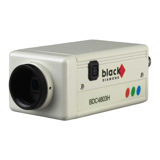
Summary of Contents for Mitsubishi Electric Black Diamond BDC4803H
-
Page 1: User Manual
CCD COLOR CAMERA BDC4803H USER MANUAL Page : 1... -
Page 2: Table Of Contents
CONTENTS CONTENTSbbbbbbbbbbbbbbbbbbbbbbbbbbbbbbbbbbbb PRECAUTIONS……………………………………… Page 3 PACKING CONTENTS...…………………………… Page 4 1. User Manual……………………………...……… 2. Camera…………………...…………………… 3. CS-Mount Adapter……………………………………… 4. Auto Iris Lens Connector……………...……………… FEATURES AND FUNCTIONS………………….… Page 5 INSTALLATION…………………………………...… Page 6 1. Power connection…………………………………….… 2. Video cable……………………………………………..… 3. Installation of the Auto Iris Lens Connector……..… 4. -
Page 3: Precautions
PRECAUTIONS PRECAUTIONS 1. Do not attempt to disassemble the camera. There are no user serviceable parts inside. Ask a qualified service person for servicing 2. Handle the camera with care. Do not misshandle the camera. Avoid striking, shaking, etc. Improper handling or storage could damage the camera. -
Page 4: Packing Contents
PACKING CONTENTS PACKING CONTENTS 1. User Manual 2. Camera 3. CS-Mount Adapter 4. Auto Iris Lens Connector Page : 4... -
Page 5: Features And Functions
FEATURES AND FUNCTIONS Auto Light Control (ALC) function Electronic Light Control (ELC) function Automatic Gain Control (AGC) function Automatic Tracing White Balance (ATW) function Internal Synchronisation Minimum Illumination of 1 Lux @ F2.0 Signal to noise ratio > 45 dB (AGC off) Horizontal resolution of 480 TV lines. -
Page 6: Installation
INSTALLATION 1. Power connection Connect the DC 12V powercable with the DC 12V Terminal. DC 12 V (± 10%) l Resistance of copper wire (at 20 °C) Copper 0,22 mm² wire size 0,078 W / m Calculation of max. cable length between camera and power supply: 10,5V DC £... -
Page 7: Video Cable
2. Video cable l It is recommended to use a monitor with a resolution at least equal to that of the camera. The max. extensible coaxial cable length between camera and the monitor is shown below. Coax cable type Recommended max. cable length (m) RG-59/U RG-6U... -
Page 8: Installation Of The Auto Iris Lens Connector
3. Installation of the Auto Iris Lens Connector Install the lens connector (YFE4191J100) when using a video drive ALC lens. The installation should be made by qualified service personnel or system installers. The pin assignment of the lens connector is as follows: Signal for video iris lens : Pin 1: Power Source + 9V DC, 50mA max. -
Page 9: Mounting The Lens
4. Mounting the Lens 1. Set up the lens by turning it clockwise on the lens mount of the camera. In case you are using a CS-Mount Lens connect the CS-Mount Adapter to the lens first and then mount it to the camera body. 2. -
Page 10: Operating Controls And Functions
5. Operating controls and functions Function switch on the back (see page: 7) Function S/W 1 Back Light Compensation Mode Selector (BLC ON, OFF) Lets you select the mode according to the position of the object and light conditions on the screen. S/W 2 Automatic Light Control / Electronic Light Control Selector (ALC;... -
Page 11: Specifications
Power Consumption Operating Temperature Operating Humidity Dimensions (W x H x D mm) (without connector) Weight (without Lens) Approvals BDC4803H C-Mount and CS-Mount (adapter) 1/3” Super HAD CCD 2:1 Interlaced H: 15.625 kHz V: 50 Hz 795 (H) x 596 (V) app. -
Page 12: Address
ADDRESS (Technical specifications subject to change. No liability will be assumed for printing errors or other errors.) Page : 12...
