Table of Contents
Advertisement
Quick Links
Advertisement
Table of Contents

Summary of Contents for Samsung MCM-A300N
- Page 1 Touch-controller_IM_03943A_1_Co_EN.indd 2 2013-06-28 오후 3:06:00...
-
Page 2: Air Conditioner
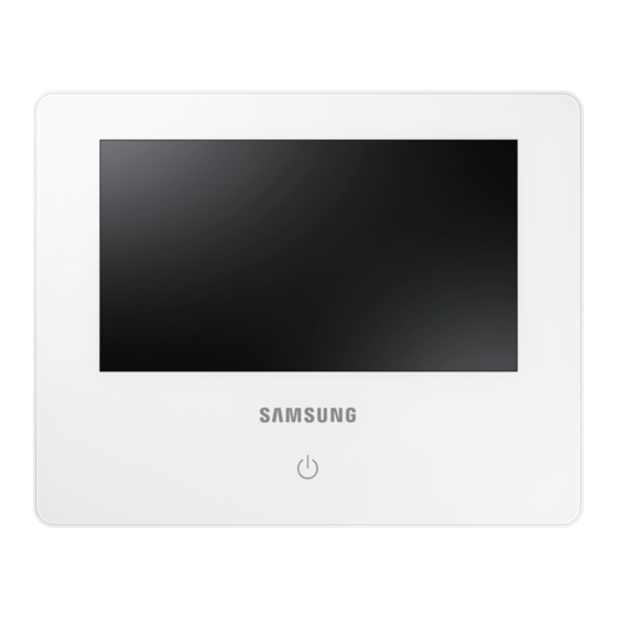
Touch Centralized Controller MCM-A300N Air Conditioner installation manual This manual is made with 100% recycled paper. imagine the possibilities Thank you for purchasing this Samsung product. EN ES FR IT PT DE EL RU AR DB68-03943A(1) Touch-controller_IM_03943A_1_Co_EN.indd 3 2013-06-28 오후 3:06:00... -
Page 3: Safety Precautions
Safety precautions This installation manual is for installing the Touch Centralized Controller. Read the installation manual thoroughly before installing the product. (Refer to the appropriate manual for installing other optional parts.) • Hazards or unsafe practices that may result in severe personal injury or death. WARNING • Hazards or unsafe practices that may result in minor personal injury or property damage. - Page 4 CAUTION SIGNS Do not install the product in a place where it is or might be exposed to inflammable gas leakage. f There is risk of fire or explosion. Do not install the product in a place where it will be exposed to oil or vapor etc. f If the product is used in a place where it is exposed to oil, vapor or sulphur dioxide, parts of the product may get damaged or product may function abnormally.
-
Page 5: Before Installation
Before installation Check list before the installation Installation cables Cables must be installed not to tightly to the wall where the product will be installed in prior to product installation. Accessories Before the installation, check if all the accessories are included with the product. Type and quantity of the accessories may be subject to change without prior notice. -
Page 6: Selecting Solderless Ring Terminal
Selecting solderless ring terminal 1. Select a solderless ring terminal for a power cable according to the nominal dimensions for cable. 2. Apply insulation coating to the connection part of the solderless ring terminal and the power cable. Silver solder Nominal dimensions for cable (mm Nominal dimensions for screw (mm) Standard dimension (mm) - Page 7 Name of the parts and product dimensions Name of the parts Front T o u c h C e n t r a l i z e d C o n t r o l l e r C o n t r o l &...
-
Page 8: Product Dimensions
Product dimensions (Unit : mm) Touch-controller_IM_03943A_1_EN.indd 7 2013-06-28 오후 3:07:04... -
Page 9: System Diagram
Installing the Touch Centralized Controller System diagram S-NET 3 TCP/IP Touch Centralized Controller OnOff controller DMS2 RS 485 Outdoor unit Touch Centralized Controller Maximum 128 indoor units (DVM series) Checking the power connection 1. Press the LCD ON/OFF button to turn on the LCD. 2. - Page 10 Maximum allowable number of connections Classification When connected to control device layer When connected to indoor/outdoor unit layer Outdoor unit 16 units 1 unit Indoor unit / ERV 128 units 80 units Installing the Touch Centralized Controller 1. Fix the installation plate of the Touch Centralized Controller on the wall with 4 screws. 2.
- Page 11 Installing the Touch Centralized Controller Tracking Through tracking function, Touch Centralized Controller searches for the device that forms a system and registers the installation & status information of those devices. 1. When you go to [Setting] [Installation settings] [Network & Tracking] menu and tap [Tracking] button, tracking will begin after user authentication.
- Page 12 DO port f DO operation specification DO output will turn on if any one of the indoor unit is turned on. DO output will turn off if all the indoor units are turned off. f DO port (+)terminal outputs 12 V, (-) terminal outputs open collector, Drive current under 10 mA.


