Table of Contents
Advertisement
Quick Links
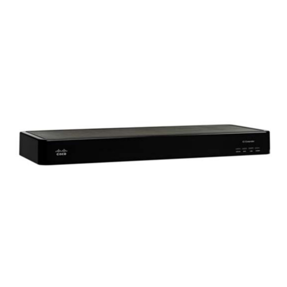
Cisco Smart+Connected I/O Extender Reference
Guide
This document provides additional information about the available ports, technical specifications and
features of the Cisco Smart+Connected I/O Extender (SCH-IO-EXT-8).
•
Overview, page 2
Package Contents, page 2
•
Requirements, page 3
•
Mounting Options, page 3
•
Installation Instructions, page 4
•
•
•
Installation Instructions, page 4
•
Connecting the Devices, page 6
•
•
Resetting the Device, page 10
•
Using the Identification Button, page 10
•
•
Specifications, page 10
•
Regulatory/Safety Information, page 11
•
Related Documentation, page 11
Warranty, page 12
•
Service and Support, page 12
•
Americas Headquarters:
Cisco Systems, Inc., 170 West Tasman Drive, San Jose, CA 95134-1706 USA
Advertisement
Table of Contents

Summary of Contents for Cisco SCH-IO-EXT-8
-
Page 1: Table Of Contents
Using the Identification Button, page 10 • • Specifications, page 10 • Regulatory/Safety Information, page 11 • Related Documentation, page 11 Warranty, page 12 • Service and Support, page 12 • Americas Headquarters: Cisco Systems, Inc., 170 West Tasman Drive, San Jose, CA 95134-1706 USA... -
Page 2: Overview
(IR), serial, contact, and relay connections. When paired with a Cisco Smart+Connected Residential Controller, the Cisco I/O Extender is ideal for expanding control in large, multiroom residences or for residences with numerous devices. -
Page 3: Requirements
Requirements Prior to installing this product, ensure that: Ethernet network wiring is in installed and functioning. Mounting Options Before installing the Cisco I/O Extender, mount the device using one of the following options. Place it on a flat surface •... -
Page 4: Installation Instructions
Step 2 cable from the network connection into the Cisco I/O Extender RJ-45 port (labeled “Ethernet”). Power up the Cisco I/O Extender: Plug the Cisco I/O Extender power cord (provided) into the Cisco I/O Step 3 Extender power plug port and then to an electrical outlet. -
Page 5: Rear View (Input And Output Ports)
Rear View (Input and Output Ports) Rear View (Input and Output Ports) Connect all applicable devices to the Cisco I/O Extender using the connection options described in the following figure. Figure 3 Rear View Power plug port—AC power receptacle for an IEC 320 power cord. -
Page 6: Connecting The Devices
“Rear View (Input and Output Ports)” section on page Pluggable Terminal Block Connectors For the contact and relay ports, the Cisco I/O Extender makes use of a pluggable terminal block connector—a removable plastic part that locks in individual wires (included). - Page 7 If you connect dry contact closure devices, such as door switches, connect the switch between +12V Note (Power) and SIG (Signal). Connect to the Contact Port The Cisco I/O Extender provides four (4) contact ports for the pluggable terminal block provided. Figure 5 through Figure 7 to learn how to connect the device to a contact port.
- Page 8 For most applications, attach one (1) wire to the common terminal, and the other to the normally open terminal. The Relay switches close when the Relay is activated. The Cisco I/O Extender can support applications that require a normally closed Contact.
-
Page 9: Configuring The Cisco I/O Extender
Setting Up IR Emitters or IR Blaster Your system may contain third-party products that are controlled through IR commands (usually using remote controls). To provide a way for the Cisco Controller to control a device that only recognizes IR commands, complete the following: Procedure Plug the 3.5 mm connector end of one of the 4 IR stick-on emitters provided into an IR Out port on the... -
Page 10: Resetting The Device
This action starts the recovery process. Using the Identification Button To reset the device to the network defaults, power cycle the Cisco I/O Extender (using the power • button on the front of the device) and hold the Identification button until the Data, Link, and Power LEDs are solid blue;... -
Page 11: Regulatory/Safety Information
–4°F to 149°F (–20°C to 65°C) Regulatory/Safety Information To review regulatory information, go to www.cisco.com/go/smartconnectedresidential/docs. Related Documentation For more information about the Cisco Smart+Connected Residential products, see the following documents and websites: Subject / Document Title Location General Product Information and Home Page www.cisco.com/go/smartconnectedresidential... -
Page 12: Warranty
Cisco and the Cisco logo are trademarks or registered trademarks of Cisco and/or its affiliates in the U.S. and other countries. To view a list of Cisco trademarks, go to this URL: www.cisco.com/go/trademarks. Third-party trademarks mentioned are the property of their respective owners. The use of the word partner does not imply a partnership relationship between Cisco and any other company. - Page 13 Service and Support Cisco Smart+Connected I/O Extender Reference Guide OL-27368-01...
- Page 14 Service and Support Cisco Smart+Connected I/O Extender Reference Guide OL-27368-01...


