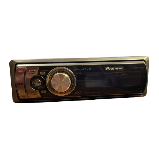
Pioneer DEH-P6800MP Operation Manual
Multi-cd control high power cd/mp3/wma/aac player with fm/am tuner
Hide thumbs
Also See for DEH-P6800MP:
- Operation manual (152 pages) ,
- Installation manual (8 pages) ,
- Service manual (80 pages)
Table of Contents
Advertisement
Quick Links
Advertisement
Table of Contents

Summary of Contents for Pioneer DEH-P6800MP
- Page 76 DEH-P6800MP This product conforms to CEMA cord colors. Le code de couleur des câbles utilisé pour ce produit est conforme à CEMA. Printed in Thailand Imprimé en Thaïlande <XRD7112-A/N> UC <KMMZX> <05H00000>...
-
Page 77: Connecting The Units
Connecting the Units Note: • This unit is for vehicles with a 12-volt battery and negative grounding. Before installing it in a recre- ational vehicle, truck, or bus, check the battery voltage. • To avoid shorts in the electrical system, be sure to disconnect the ≠... - Page 78 When not connecting a rear speaker lead to a Subwoofer Antenna jack 15 cm (5-7/8 in.) This product Subwoofer output Jack for the Wired Remote Control Please see the Instruction Manual for the Wired Remote Control (sold separately). Yellow/black If you use an equipment with Mute function, wire this lead to the Audio Mute lead on that equipment.
- Page 79 Connecting the Units When using a Subwoofer without using the optional amplifier Antenna jack 15 cm (5-7/8 in.) This product Subwoofer output Jack for the Wired Remote Control Please see the Instruction Manual for the Wired Remote Control (sold separately). Yellow/black If you use an equipment with Mute function, wire this lead to the Audio Mute lead on that equipment.
- Page 80 Note: • Before making a final installation of the unit, tem- porarily connect the wiring to confirm that the con- nections are correct and the system works properly. • Use only the parts included with the unit to ensure proper installation. The use of unauthorized parts can cause malfunctions.
- Page 81 Removing the unit (Fig. 6) (Fig. 7) Frame To remove the frame, extend top and bottom of the frame outwards in order to unlock it. (When reattaching the frame, point the side with a groove downwards and attach it.) • It becomes easy to remove the frame if the front panel is released.
- Page 82 DIN Rear-mount Installation using the screw holes on the side of the unit 1. Remove the frame. (Fig. 8) 2. Fastening the unit to the factory radio mounting bracket. (Fig. 9) (Fig. 10) Select a position where the screw holes of the bracket and the screw holes of the head unit become aligned (are fitted), and tighten the screws at 2 places on each side.
- Page 83 Fixing the front panel If you do not operate the removing and attaching the front panel function, use the supplied fixing screw to fix the front panel to this unit. Fixing screw Fig. 11...


