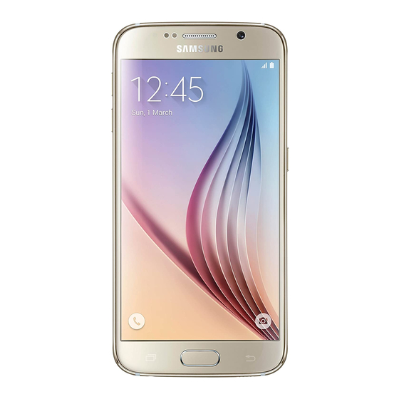
Samsung Galaxy S6 Repair Manual
5s chargeport
Hide thumbs
Also See for Galaxy S6:
- Instruction manual (535 pages) ,
- User manual (423 pages) ,
- Important information manual (60 pages)
Advertisement
Advertisement
Table of Contents

Summary of Contents for Samsung Galaxy S6
- Page 1 Galaxy S6 Glass/Lcd REPAIR GUIDE Version 1 2016 Edition...
- Page 2 Samsung Galaxy 5s chargeport REPAIR GUIDE RiAna Soto Repair Training Specialist rsoto@cellairis.com...
- Page 3 FOR EVERY REPAIR MAKE SURE TO COMPLETE, INITIAL, AND HAVE CUSTOMER SIGN THE CELLAIRIS REPAIR LIABILITY WAIVER FORM...
- Page 4 PRE-REPAIR DEVICE CHECK-IN...
- Page 5 TOOLS NEEDED • Philips screwdriver • Spudger • Tweezers • Isesamo • Pentalobe screwdriver • Magnetic Mat • IPhone 5/5s replacement Chargeport...
- Page 6 HEAT-GUN PRECAUTIONS Always operate the heat gun on the lowest setting. • Keep face, hands, hair, and clothing away from the air stream. • The air nozzle also becomes extremely hot. Never grab the heat gun by the nozzle. • Never operate the heat gun by laying it on its side on a table.
- Page 7 ADDITIONAL PRECAUTIONS Magnetic Pad: During the repair, you will be utilizing a magnetic pad to organize the plethora of • differing screws that you will be pulling out of the iPhone 6S. Below is a list of several internal components of the iPhone 6S that should never be placed on the pad, or you risk damaging the hardware or erasing client data: LCD/Digitizer Assembly •...
- Page 8 ADDITIONAL PRECAUTIONS Power on/off: To avoid any damage to the hardware during the repair, it is best to have the device • powered off until you can get to and disconnect the battery. Battery: Never unplug any flex cables unless the battery has been completely disconnected to avoid •...
- Page 9 LET’S START!
- Page 10 Tools: Pentalobe screwdriver STEP 1 Disassemble the device • Power off device. • Remove the bottom two (2) pentalobe screws using the pentalobe screwdriver. • Take the isesamo tool and slide it in between frame of phone and bezel to open device. Keep in mind the iPhone 5s has a home button flex cable attached to the screen so this needs to be disconnected before completely opening the screen.
- Page 11 Tools: spudger, Philips screwdriver STEP 2 • Once the home button flex cable is Disassemble the device disconnected screen will be lifted open. • Disconnect the battery by removing metal bracket covering battery cable and disconnect. • Next, disconnect the Digitizer/LCD and proximity sensor cables to remove screen by taking off the EMI shield held down by four (4) Philips screws.
- Page 12 Tips: Tools: spudger The chargeport, audio jack and STEP 3 microphone are all one part that will be taken out. Two things attached to Disassemble the device original part will be transferred to new part. • Now that the screen is removed we will go back down to the chargeport flex cable and disconnect using the flat end of the spudger.
- Page 13 Tips: make sure to keep screws Tools: Spudger, fingers organized on magnetic mat. STEP 4 Disassemble the device • Remove standoff screw next to antenna. • Next we will remove the two Philips screws at the bottom of the loud speaker. •...
- Page 14 Tools: spudger STEP 5 Disassemble the device • Remove the five (5) Philips screws and make sure to keep them organized so you will be able to put them back in the right places. • Next, use the spudger to get underneath the chargeport flex cable to lift up and out.
- Page 15 Tools: spudger, tweezers STEP 6 Disassemble the device • Now that the original part is removed underneath you will notice a metal bracket and metal washer they sometimes will Original come lose make sure to keep those in the device in the correct position.
- Page 16 Tools: Philips screwdriver, Tip: peel blue or red covering spudger off adhesive so the new part STEP 1 will stay in place. Reassemble the device • Those pieces are now transferred over so put the new replacement part back into the device.
- Page 17 Tools: Philips screwdriver, spudger, Fingers Tips: take your time so everything is fitting accordingly. STEP 2 • After positioned properly screw in the five (5) Philip screws. • Slide the loud speaker into the place by taking the long end and slide it underneath the home button flex connector and simultaneously get the top of the loud speaker prong under the motherboard.
- Page 18 Tools: Philips screwdriver, spudger, Fingers Tips: take your time so everything is fitting accordingly. STEP 3 • Next, reconnect the antenna. • Reconnect the chargeport flex cable. • Next reconnect the Digitizer/LCD and proximity cable to assemble screen back. Screw the EMI shield back into place.
- Page 19 Tools: Philips screwdriver, spudger, Fingers Tips: take your time so everything is fitting accordingly. STEP 4 • Connect battery and put metal bracket back over battery and screw in the two (2) Philips screws. • Reconnect home button flex cable and place metal bracket over connector, before closing the screen.
- Page 20 Tools: Pentalobe screwdriver STEP 5 Reassemble the device • Final step is to screw the two (2) pentalobe screws into the bottom of the phone with the pentalobe screwdriver. At this point power on device and run a post test to check functionality and make any notes on customer check-in device sheet.
-
Page 21: Troubleshooting
STEP 6 Troubleshooting • If you notice the charger won’t snap all the way into the connector most likely the charging port isn’t all the way in. This will result in you opening the phone back up and adjusting the port push all the way in. - Page 22 C O N T A C T Riana Soto REPAIR 678.513.4020 x400 TRAINING rsoto@cellairis.com...


