Table of Contents
Advertisement
Quick Links
Advertisement
Table of Contents

Summary of Contents for Toshiba GRT100
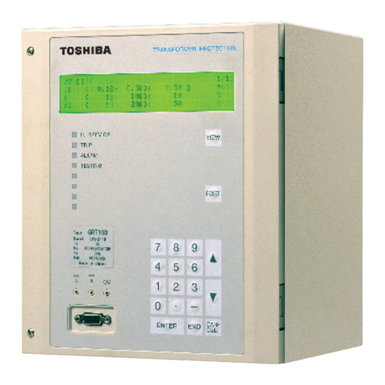
- Page 2 RS485 port at the rear of the relay. Metering and recording functions Menu-driven user interface GRT100 has two models which differ according to the Two serial ports for a local PC and a remote PC number of three-phase current inputs for differential protection.
- Page 3 Employing residual current of each winding and Current Differential Protection neutral point current, Restricted Earth Fault (REF) GRT100 provides fast, selective protection for two- protection provides a highly sensitive differential and three-winding transformers. It has three phase- protection for earth faults in a transformer which has segregated differential elements, each with a dual- a star point directly earthed or low impedance earthed.
- Page 4 : Time for alarm Trip Alarm K ⋅ I B Figure 4. Characteristic of thermal overload element Frequency Protection GRT100 has two frequency elements, which provide the following schemes: Underfrequency protection Overfrequency protection Figure 3. Characteristics of inverse time delayed overcurrent element...
- Page 5 GRT100 Overexcitation Protection Trip and/or Indication of External Protection Devices A single phase to phase connected voltage input is provided to detect overexcitation. Alarms and tripping, External signals such as overpressure devices and based on a measurement of the voltage/frequency Buchholz relay operation, can be applied through 4 ratio are provided.
- Page 6 GRT100 The terminal blocks are located at the rear of the to analog data, phase currents, neutral current and relay providing connections for all input/output circuits. phase to phase voltage are recorded. The relay is housed in a type-A case, suitable for...
- Page 7 Local PC Relay Setting The user can communicate with the GRT100 from a local PC via the RS232C port on the relay fascia. The The user can input or change settings using the following data can be viewed or analysed on the local operation keys on the relay fascia or via a local or PC with RSM100 software.
- Page 8 GRT100 PC DISPLAY Fault record Waveform data analysis Event record Vector diagram AUTOMATIC MONITORING Automatic Monitoring Function The automatic monitoring function will detect failures, should they occur, that might cause unwanted operation. The items monitored include the following: - Analog input circuits...
- Page 9 GRT100 TECHNICAL DATA Ratings AC current 1A or 5A AC voltage 100V, 110V, 115V, 120V Frequency 50Hz or 60Hz DC power supply 110Vdc/125Vdc (Operative range: 88 to 150Vdc) 220Vdc/250Vdc (Operative range: 176 to 300Vdc) 48Vdc/54Vdc/60Vdc (Operative range: 38.4 to 72Vdc)
- Page 10 GRT100 Time-overcurrent protection High-set overcurrent element Pick up level (OC, EF) 0.10 to 20.00pu in 0.10pu steps Delay time (TOC, TEF) 0.00 to 10.00s in 0.01s steps Operating time typical 30ms (without delay time) Inverse time overcurrent element Pick up level (OCI, EFI) 0.10 to 5.00pu in 0.01pu steps...
- Page 11 GRT100 Communication port Front communication port (local PC) Connection Point to point Cable type Multi-core (straight) Cable length 15m (max.) Connector RS232C 9-pin D-subminiature connector female Rear communication port (remote PC) RS485 I/F: 64kbps Transmission data rate for RSM system Connection Multidrop mode (max.
- Page 12 GRT100 ENVIRONMENTAL PERFORMANCE Test Standards Details Atmospheric Environment Temperature IEC60068-2-1/2 Operating range: -10°C to +55°C. Storage / Transit: -25°C to +70°C. Humidity IEC60068-2-78 56 days at 40°C and 93% relative humidity. Enclosure Protection IEC60529 IP51 (Rear: IP20) Mechanical Environment Vibration...
- Page 13 GRT100 Test Standards Details European Commission Directives 89/336/EEC Compliance with the European Commission Electromagnetic Compatibility Directive is demonstrated according to EN 61000-6-2 and EN 61000-6-4. 73/23/EEC Compliance with the European Commission Low Voltage Directive is demonstrated according to EN 50178 and EN 60255-5.
- Page 14 GRT100 ORDERING 1. Transformer Protection GRT100 − B − 0 − Type: Transformer Protection Relay GRT100 Model: -Model 100: 2 three-phase current inputs for 2-winding transformer -13 N/O configurable output contacts -23 N/O configurable output contacts -Model 200 : 3 three-phase current inputs for 3-winding transformer...
- Page 15 GRT100 RELAY OUTLINE Panel Surface mount M3.5 Ring terminal M3.5 Ring terminal Figure 10. Relay case Type-A outline for surface mount 19-inch rack mount Figure 11. Relay case Type-A outline for rack mount...
- Page 16 GRT100 EXTERNAL CONNECTION DIAGRAM OUTPUT CONTACTS SIGNAL LIST (DEFAULT) TB3-A2 TB1 -1 TRIP-1 TRIP-2 DIFT 1OC, 1OCI 2OC, 2OCI 1REF, 1EF, 1EFI 2REF, 2EF, 2EFI V/F TRIP BO10 V/F ALARM BO11 THR TRIP BO12 THR ALARM BO13 MEC. RIP-1/ -2/ -3/ -4...
- Page 17 GRT100 TB2-A1 OUTPUT CONTACTS TB3-A2 SIGNAL LIST (DEFAULT) TB1 -1 TRIP-1 TRIP-2 DIFT 1OC, 1OCI 2OC, 2OCI 1REF 2REF, 1EF, 1EFI 2EF, 2EFI BO10 BO11 V/F (T) TRIP BO12 V/F (H) TRIP BO13 V/F ALARM THR TRIP THR ALARM TRIP-1...
- Page 18 GRT100 TB1 -1 TB3-A2 OUTPUT CONTACTS SIGNAL LIST (DEFAULT) TRIP-1 TRIP-2 TRIP-3 DIFT 1OC, 1OCI, 1REF, 1EF, 1EFI 2OC, 2OCI, 2REF, 2EF, 2EFI 3OC, 3OCI, 3REF, 3EF, 3EFI V/F TRIP BO10 V/F ALARM BO11 THR TRIP BO12 THR ALARM BO13 MEC.
- Page 19 GRT100 TB2-A1 OUTPUT CONTACTS TB1 -1 TB3-A2 SIGNAL LIST (DEFAULT) TRIP-1 TRIP-2 TRIP-3 DIFT 1OC, 1OCI 2OC, 2OCI 3OC, 3OCI 1REF 2REF BO10 3REF BO11 1EF, 1EFI BO12 2EF, 2EFI BO13 3EF, 3EFI V/F (T) TRIP V/F (H) TRIP V/F ALARM...
- Page 20 Industrial and Power Systems & Services Company 1-1,SHIBAURA 1-CHOME,MINATO-KU, TOKYO 105-8001,JAPAN PHONE;+81-3-3457-3644 FAX;+81-3-5444-9168 http://www.toshiba.co.jp/f-ene/tands/english/protect/f_pc_top.htm The data given in this catalog are subject to change without notice. 6639-1 0508T1...
