Advertisement
Quick Links
Installation Instructions
Model ALD-2I
AnaIog Loop Driver
OPERATION
The Model ALD-2I from Siemens Industry, Inc.
is an optional MXL/MXLV/MXL-IQ network
module that connects intelligent addressable
devices to the MXL/MXLV/MXL-IQ System.
The module uses two consecutive network
addresses on the System. Devices connected
to the ALD-2I circuits are supervised by the
MXL Control Panel.
Each of the ALD-2I circuits supports up to 60
alarm causing, trouble causing, security, and
supervisory type devices, as well as remote
CZM-1s and intelligent output devices. Each
device has its own address. The sensitivity of
any intelligent smoke detector is checked and
Siemens Industry, Inc.
Building Technologies Division
Florham Park, NJ
P/N 315-091464-13
adjusted from the Control Panel. Sensitivity, as
well as other device information, is displayed at
the Control Panel. The ALD-2I also supports the
use of relay bases.
Each ALD-2I circuit can be wired in either a Class
B or Class A configuration. When using Class B,
T-tapping is permitted with no loss of supervision.
The ALD-2I module has an on-board micro-
processor which provides it with the ability to
function and to initiate alarm conditions even if
the MXL main processor fails. The module also
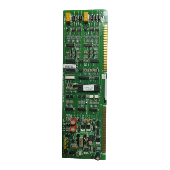
has four LEDs, which can indicate alarm, trouble,
transmit, or ground fault. (Refer to Figure 1.)
Figure 1
ALD-2I Board
Siemens Building Technologies, Ltd.
Fire Safety & Security Products
2 Kenview Boulevard
Brampton, Ontario
L6T 5E4 Canada
Advertisement

Summary of Contents for Siemens ALD-2I
- Page 1 MXL/MXLV/MXL-IQ System. use of relay bases. The module uses two consecutive network Each ALD-2I circuit can be wired in either a Class addresses on the System. Devices connected B or Class A configuration. When using Class B, to the ALD-2I circuits are supervised by the T-tapping is permitted with no loss of supervision.
- Page 2 INSTALLATION After the address is set, install the ALD-2I in the Remove all system power before installation, first battery then AC. (To power up, connect the MOM-4, being sure that the module is riding in the card guides and is firmly seated in the card AC first, then the battery.)
- Page 3 DEVICE INITIATING DEVICE NOT USED MOM-4 10 11 12 13 14 15 16 TB 1 TB 2 LOOP 1 LOOP 2 Figure 3 OPERATES IN FULL CONFORMANCE WITH STYLE 6 ALD-2I Wiring Diagram OPERATES IN FULL CONFORMANCE WITH STYLE 4...
- Page 4 P/N 315-091464-13...


