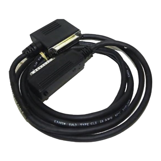
Summary of Contents for GE IC693CBL300
- Page 1 QuickPanel™ Control Communication Module Quick Installation Guide PCIF I/O Adapter April 2010 GFK-2245A...
- Page 2 Features may be described herein which are not present in all hardware and software systems. GE Intelligent Platforms as- sumes no obligation of notice to holders of this document with respect to changes subse- quently made.
- Page 3 Contact Information If you purchased this product through an Authorized Channel Partner, please contact the seller directly. General Contact Information Online technical support and GlobalCare http://www.ge-ip.com/support Additional information http://www.ge-ip.com/ Solution Provider solutionprovider.ip@ge.com Technical Support If you have technical problems that cannot be resolved with the information in this guide, please contact us by telephone or email, or on the web at www.ge-ip.com/support...
- Page 4 Contact Information Europe, the Middle East, and Africa Online Technical Support www.ge-ip.com/support Phone +800-1-433-26 EMEA Direct Dial +352-26-722-780 (if toll free 800 option is unavail- able or if dialing from a mobile telephone) Technical Support Email support.emea.ip@ge.com Customer Care Email customercare.emea.ip@ge.com...
- Page 5 The PCIF I/O Adapter has been tested and found to meet or exceed the requirements of U.S. (47 CFR 15), Canadian (ICES-003), Australian (AS/NZS 3548) and European (EN55022) regulations for Class A digital devices when installed in accordance with guide- lines noted in this manual.
-
Page 6: Installing A Communication Module
Installation Installing a Communication Module Warning: Always use anti-static precautions when ac- cessing the mating connector or the interior of the unit. Note: The 6” model QuickPanel is shown. Other models are similar. Disconnect the DC input power terminal block connec- tor from your QuickPanel Control unit before connect- ing the Communication Module to the unit. - Page 7 Installation 7 Open the back cover. Attach the Communication Module to the unit by plug- ging the module into the mating connectors on the back of the unit. Install the three screws to secure the card in the unit. Close the cover. Connect your I/O network to external connections on the module enclosure (see applicable sections for details).
- Page 8 8 Specification Series 90-30 Remote I/O Connector Pin # Signal Direction SHLD 2 DFRAM Output 3 DFRAM Output 8 RUN Output 9 RUN Output 12 P ERR + Input 13 P ERR - Input 16 DA TA + Input/Output 17 DA TA - Input/Output 20 R...
-
Page 9: Installation
(Belden 8107 or equivalent). The final rack on the I/O Bus should be terminated with an I/O Bus terminator plug, catalog number IC693ACC307. Interconnecting cables may be standard length GE expan- sion cables or custom length cables. Part Number...


