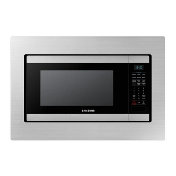
Summary of Contents for Samsung MA-TK8020 Series
- Page 1 Built-in Trim Kit Installation Instructions MA-TK8020** MA-TK8020_AA_II_DE68-04476B-00_EN+CFR.indb 1 2018-01-18 4:40:35...
- Page 2 Contents Contents Before you begin READ THESE INSTRUCTIONS COMPLETELY AND CAREFULLY. Before you begin IMPORTANT Parts included in the kits • Save these instructions for local inspector’s use. • Observe all governing codes and coordinates. Tools needed • Be sure to disconnect the plug of the microwave oven from the electrical outlet before installing the Builtin Kit.
- Page 3 Parts included in the kits Tools needed Screwdriver Pencil Drill with 7/64” or #35 Drill bit Trim Frame (1 EA) Duct Base (1 EA) Duct Side (1 EA) Scissors Tape measure T15H Torx driver Duct Rear (1 EA) Install Bracket (2 EA) Install hook Screw A Screw B...
- Page 4 Installation Installation STEP 2 STEP 1 CUTOUT DIMENSIONS Height 16 3/4" ± 1/16" Width 25 1/2" ± 1/16" CENTER Width Depth 21 1/2" ± 1/16" LINE Height TRIM DIMENSIONS Depth Height 20 1/16" ± 1/64" 3" min Electric Heat Width 29 3/4"...
- Page 5 STEP 4 4. Tight 2 screws together on the Install hook by using provided 1. Place oven on the Duct Base. SCREW A. (2 EA) NOTE You may not be assembled when using the thicker Drill bit. Duct Base 2. Tight 2 screws together on the STEP 3 back side with Duct base by using provided SCREW C.
- Page 6 Installation STEP 5 4. Tight 4 screws to Duct base and Duct side on the left side by using 1. Slide the oven with Duct Base into provided SCREW C. (4 EA) Check the assembly cabinet until Duct Base touch the between Install hook Duct Side front of cabinet.
- Page 7 5. Tight Install Bracket 4 holes by 2. Open the oven door. Tight 4 screws using provided SCREW A. (4 EA) Trim frame by using provided SCREW B. (4 EA) STEP 6 1. Press the Trim Frame into the opening until all sides snap into place.
- Page 8 DE68-04476B-00 MA-TK8020_AA_II_DE68-04476B-00_EN+CFR.indb 8 2018-01-18 4:40:38...
- Page 9 Kit de garniture intégré Consignes d'installation MA-TK8020** MA-TK8020_AA_II_DE68-04476B-00_EN+CFR.indb 1 2018-01-18 4:40:40...
- Page 10 Table des matières Table des matières Avant de commencer LISEZ ENTIÈREMENT ET ATTENTIVEMENT CES INSTRUCTIONS. Avant de commencer IMPORTANT Pièces incluses dans le kit • Conservez ces instructions pour pouvoir les remettre à l'inspecteur local en cas de passage. Outils requis •...
- Page 11 Pièces incluses dans le kit Outils requis Tournevis Crayon Percez avec un foret de 7/64" ou n° 35. Bâti d'encastrement Base de passage de câble Partie latérale de passage (x1) (x1) de câble (x1) Ciseaux Mètre à ruban Tournevis Torx T15H Partie arrière de passage de Support d'installation Crochet d'installation...
- Page 12 Installation Installation ÉTAPE 2 ÉTAPE 1 DIMENSIONS DU RENFONCEMENT Hauteur 16 3/4" ± 1/16" Largeur 25 1/2" ± 1/16" LIGNE Largeur CENTRALE Profondeur 21 1/2" ± 1/16" Hauteur DIMENSIONS DE LA GARNITURE Profondeur Hauteur 20 1/16" ± 1/64" 3" minimum Modèle à...
- Page 13 ÉTAPE 4 4. Serrez les deux vis en même temps sur le crochet d'installation à l'aide 1. Placez le four sur la base de des VIS A (x2) fournies. passage de câble. REMARQUE Il se peut que vous ne puissiez pas assembler si vous utilisez un foret plus épais.
- Page 14 Installation ÉTAPE 5 4. Serrez les quatre vis sur la base de passage de câble et la partie 1. Faites glisser le four avec la latérale de passage de câble à Vérifiez le bon assemblage entre le base de passage de câble dans le l'aide des VIS C (x4) fournies.
- Page 15 5. Serrez le support d'installation 2. Ouvrez la porte du four. Serrez les au niveau des 4 trous à l'aide des quatre vis du bâti d'encastrement à VIS A (x4) fournies. l'aide des VIS B (x4) fournies. ÉTAPE 6 1. Poussez le bâti d'encastrement dans l'ouverture jusqu'à...
- Page 16 DE68-04476B-00 MA-TK8020_AA_II_DE68-04476B-00_EN+CFR.indb 8 2018-01-18 4:40:44...


