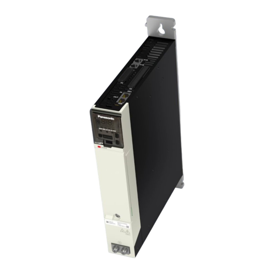
Panasonic MINAS A6 Multi Quick Start Manual
Hide thumbs
Also See for MINAS A6 Multi:
- Operating instructions manual (560 pages) ,
- Technical reference (306 pages) ,
- Reference specifications (70 pages)
Summary of Contents for Panasonic MINAS A6 Multi
- Page 1 Servo Drives Quick Start Guide MINAS A6 Multi PANATERM for Safety Safe Torque Off (STO) QS10002_V1.0_EN 2020.11 https://industry.panasonic.eu...
- Page 2 This manual and everything described in it are copyrighted. You may not copy this manual, in whole or part, without written consent of Panasonic Electric Works Europe AG (PEWEU). PEWEU pursues a policy of continuous improvement of the design and performance of its products.
-
Page 3: Table Of Contents
1.4 Available software..........................5 2 Functional overview........................6 3 Wiring............................8 3.1 Basic wiring of the MINAS A6 Multi....................8 3.2 Wiring of the emergency stop button....................8 3.3 USB license dongle.......................... 9 3.4 Connect the PC and the driver module................... 9 4 Functional safety configuration.................... -
Page 4: Introduction
Electrical connections must be made by qualified electrical personnel. About this document This “Quick Start Guide” is intended to help you set up a MINAS A6 Multi servo drive system. It is based on information from the MINAS A6 Multi series manuals and the practical experience of our engineers. -
Page 5: Available Software
“Recommendations for EMC-compliant wiring of servo drivers and motors” • Related Quick Start Guides: “QS10000, MINAS A6 Multi, Position control with Beckhoff host controller over EtherCAT” “QS10001, MINAS A6 Multi, Ethernet over EtherCAT with PANATERM” “QS10003, MINAS A6 Multi, Safe Stop 1 (SS1)”... -
Page 6: Functional Overview
Use the following accessories: • 1 x 400V AC power supply cable Connects the MINAS A6 Multi power supply module to the main power supply (400V AC). • 1 x 24V DC power supply cable Connects the power supply unit (24V DC) and the host controller. - Page 7 (6) MINAS A6 servo motor B (1.5kW) (7) MINAS A6 servo motor A (1kW) (8) USB license dongle for PANATERM for Safety (9) PC with PANATERM for Safety Set-up of a MINAS A6 Multi servo drive system - Safe Torque Off (STO) QS10002_V1.0_EN...
-
Page 8: Wiring
• PE terminals of power supply module and driver module connected by grounding wire For details on how to do the wiring of the MINAS A6 Multi servo drive system, refer to “Wiring” in “QS10000, MINAS A6 Multi, Position control with Beckhoff host controller over EtherCAT”. -
Page 9: Usb License Dongle
3 Wiring +24V +24V Pin 15 +24V Pin 32 Pin 15: Grouped safety digital input 1A Pin 16: Safety input common A Pin 17: External power supply (24V DC) for safety I/O Pin 32: Grouped safety digital input 1B Pin 33: Safety input common B Pin 34: External ground USB license dongle A USB license dongle is required to compile and download the functional safety... - Page 10 3 Wiring (1) X8: USB connector on driver module QS10002_V1.0_EN...
-
Page 11: Functional Safety Configuration
Install PANATERM for Safety on your PC The programming software PANATERM for Safety provides a graphical environment to create PLC-based monitoring programs for the MINAS A6 Multi servo drive system. Install the software on your PC. For details, refer to the “SX-DSV03508, MINAS A6 Multi, Programming Manual –... - Page 12 4 Functional safety configuration Select “Library” and then “MINAS A6 Multi” under “New document device group”. Select “MINAS A6 Multi 2 Axis” from the “Library” window and drag the element into the “Terminal Scheme” window. Go to the “Properties” window and select the A6 encoder for both axes.
- Page 13 4 Functional safety configuration Go to the “Library” window, select the “Emergency Stop” element and drag it into the “Terminal Scheme” window. Select the “Emergency Stop” element in the “Terminal Scheme” window, and make the settings in the “Properties” window as shown in the screenshot. Go to the “Functional Scheme”...
-
Page 14: Download The Safety Program To The Driver Module
4 Functional safety configuration Select the safety function “[STO] Safety Torque Off” from the “Library” window and drag it into the “Functional Scheme” window. Use the mouse to connect the elements. Select “Check + Compile” in the ribbon to compile your project Download the safety program to the driver module Remember that a USB license dongle is required to compile and save your program. - Page 15 4 Functional safety configuration Select “Connection Settings” in the ribbon and then “USB Cable”. Select “Connect” in the ribbon. Select “Send Configuration” in the ribbon. Select “Yes” to confirm the message that this action will change the device state. Wait until the configuration is transmitted to the driver module and then reboot the driver module.
- Page 16 4 Functional safety configuration To check the current status of the safety function, go to “Diagnostics” and select the “Functional Scheme” window. A yellow line means that the emergency stop button was not yet pressed. If it is red, the emergency button has been pressed and STO is active.
-
Page 17: Help Us Improve
Please feel free to contact us if you have any questions, or if you have any suggestions for improvement. In that case, we ask you to include the Quick Start Guide number in the email subject line. You can find the number starting with "QS" on the cover page. servo.peweu@eu.panasonic.com +49 (0) 8945354-2750 QS10002_V1.0_EN... -
Page 18: Record Of Changes
6 Record of changes Record of changes QS10002_V1.0_EN, 2020.11 First edition QS10002_V1.0_EN... -
Page 19: Panasonic Hotline
7 Panasonic hotline Panasonic hotline If you have questions that cannot be clarified by the manuals or online help, please contact your sales office. Europe Austria: 02236 / 2 68 46, info.pewat@eu.panasonic.com Benelux: 0499 / 37 27 27, info.pewswe@eu.panasonic.com France: 01 / 60 13 57 57, info.pewswef@eu.panasonic.com...


