Table of Contents
Advertisement
Quick Links
Advertisement
Table of Contents

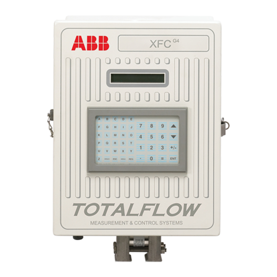
Summary of Contents for ABB Totalflow X Series
- Page 1 SERIES Series Start-Up Guide...
- Page 2 Introduction: This startup guide is to assist in the startup of any flow computer or remote controller of the XFC (flow computer) or XRC (remote controller) series. It is however, primarily intended for gas orifice applications. It is hoped that this guide in conjunction with other drawings and documentation that accompanies your order will result in a smooth installation.
- Page 3 2" x 40" M o unting Pip e Sad d le M eter Run "U " M o unting Bo lt Figure 1 (Saddle Mount) Flat and lock washers with 9/16" bolt U - Bolt 2 " Mounting Pipe Figure 2 (Pipe Mount) Figure 3 (Typical Manifold Mount)
- Page 4 Install RTD Probe: 7. Install RTD and connect wiring to connector block J7 on the XFC board. The XRC board does not have RTD inputs. (See Figure 5) Install Battery(s): 8. Verify that Memory Backup is Enabled. This is J13 on the XFC and J1 on the XRC.
- Page 5 17. If calibration is needed, calibrate static pressure first, then differential pressure, using a deadweight tester or acceptable standard. Insure that both orifice taps are closed and bypass valves are open during AP calibration to avoid a false DP. Make sure there are no leaks in the manifold or test equipment.
- Page 6 Installing and Wiring RTD and Probe The RTD measures flowing gas temperature. Procedures presented in this section enable the user to install the RTD into the meter run and wire leads to the main electronics board. This procedure is for the XFC; the XRC does not have RTD inputs.
-
Page 7: Battery Installation
Battery Installation 1. To extend the life of the battery pack, fully charge the battery prior to installation. A system using solar panels may not fully charge the battery. Also a fast charge, which the solar panel can’t provide, improves the life of the battery. (See tip below) 2. -
Page 8: Solar Panel Installation
Solar Panel Installation • Totalflow One Solar Panel and Cable • Materials Two U-Bolts and fastening hardware • Supplied One Solar Panel Bracket • Cable Ties Customer • One 9-inch or greater extension of 2-inch pipe Materials • One 2-inch collar Supplied Procedure: Note: Step 1 and 2 are not required if pipe is tall enough without the... - Page 9 Solar Panel Mounting Bracket U - Bolts 2 " Extension Pipe Solar Panel Cable 2 " Collar Flow Computer Figure 4 (Solar Panel Mounting)
- Page 10 • • • • • • • • • • • • • • • • • • • • • • • • • • • • • • • • • • • • • • • • •...
- Page 11 Figure 6 (XRC Layout) NOTE: Refer to Wiring Interconnect drawing 2015225-WI for more information on communications wiring.
-
Page 12: Remote Communications
Remote Communications The following discussion deals primarily with the unit communicating with the Host (typically WinCCU). To communicate with the Host, the XFC or XRC has remote communication’s ports that can function as RS232, RS485 or RS422. Depending on the customer’s order, most units are shipped with the appropriate wiring in place for the specified communication’s equipment. -
Page 13: Communications Troubleshooting
Communications Troubleshooting A new radio or modem system that doesn’t communicate is difficult to troubleshoot because proper operation has never been proven, and all the initial hardware and software settings are suspect. More than one problem can be present, causing component replacement to be an inadequate trouble shooting technique. - Page 14 Users in other countries will need to consult with their local telephone company. Wiring Specific wiring drawings are sent with each unit, based on the options ordered. Most wiring diagrams, including communications are available on the web at http://www.abb.com/totalflow. Select “Continuing Customer Service Support”, then select “Wiring...
-
Page 15: Standard Displays
Standard Displays Items that appear on the unit’s display are programmable by the user, however based on the measurement application; units will be shipped with some default display items. The following table is a typical set of default displays for an AGA-3 application. Engineering units may vary from those shown if the unit supports the “Selectable Units”... - Page 16 Visual Alarm & Status Codes After the unit completes recording of Log Period flow and operational records, the LCD will show any alarm conditions that have occurred. Also, the date, hour and type of alarm conditions are stored in the device’s memory.
- Page 17 Table 1 Alarm & Status - Codes and Description Alarm/ Status Description Codes I/O Subsystem Low Lithium Battery Alarm: When (low lithium) is displayed; lithium battery voltage is below 2.5 VDC. A new lithium battery measures approximately 3.6 VDC. Low Charger: Displayed if the battery charging voltage is less than 0.4 VDC greater than the battery voltage.
- Page 18 MODBUS ASCII: Modbus ASCII protocol is selected for this port. MODBUS RTU: Modbus RTU protocol is selected for this port. Local Protocol: Displayed when PCCU32 port is active and running Totalflow Local Protocol. ¥ Packet Protocol: Totalflow Packet Protocol is active on this port.
- Page 19 Measurement Applications Back Flow Condition: Visible only when DP variable displayed. Zero Flow Condition: Visible only when Flow Rate displayed. Hold: Displayed when PCCU32 is in Calibration Mode and has a measurement application in Hold mode. Alarm Condition: Need to view alarm. You may need to compare application limits to current values to determine where the alarm condition is present.
- Page 20 ABB Inc. Totalflow Products 7051 Industrial Blvd. Bartlesville, Oklahoma 74006 Tel: USA (800) 442-3097 International 001-918-338-4880...


