Table of Contents
Advertisement
Quick Links
This service information is designed for experienced repair technicians only and is not designed for use by the general public.
It does not contain warnings or cautions to advise non-technical individuals of potential dangers in attempting to service a product.
Products powered by electricity should be serviced or repaired only by experienced professional technicians. Any attempt to
service or repair the product or products dealt with in this service information by anyone else could result in serious injury or death.
In order to avoid frostbite, be assured of no refrigerant leakage during the installation or repairing of refrigerant circuit.
WARNING
PRECAUTION OF LOW TEMPERATURE
Order No: PAPAMY1502019CE
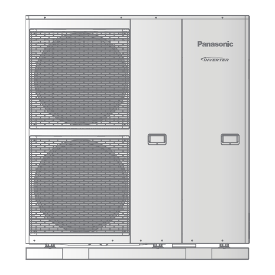
Mono bloc Unit
WH-MXC09G3E8
WH-MXC12G9E8
Destination
Europe
Turkey
© Panasonic Corporation 2015.
Advertisement
Table of Contents

Summary of Contents for Panasonic WH-MXC09G3E8
- Page 1 PRECAUTION OF LOW TEMPERATURE In order to avoid frostbite, be assured of no refrigerant leakage during the installation or repairing of refrigerant circuit. © Panasonic Corporation 2015.
-
Page 2: Safety Precautions
1. Safety Precautions Read the following “SAFETY PRECAUTIONS” carefully before installation of (Mono bloc) Air-to-Water Heatpump system (hereafter referred to as “Mono bloc unit”). Electrical works and water installation works must be done by licensed electrician and licensed water system installer respectively. - Page 3 WARNING This equipment is strongly recommended to be installed with Residual Current Device (RCD) on-site according to the respective national wiring rules or country-specific safety measures in terms of residual current. The unit is only for use in a closed water system. Utilization in an open water system may lead to excessive corrosion of the water piping and risk of incubating bacteria colonies, particularly Legionella, in water.
-
Page 4: Specifications
2. Specifications WH-MXC09G3E8 Item Unit Refrigerant System Performance Test Condition EN14511 Cooling Condition (Ambient/Water) A35W7 Cooling Capacity 7.00 BTU/h 23900 kcal/h 6020 3.17 kcal/hW 2.72 Heating Condition (Ambient/Water) A7W35 A2W35 Heating Capacity 9.00 9.00 BTU/h 30700 30700 kcal/h 7740 7740 4.84... - Page 5 Item Unit Mono bloc Unit Cooling: 2.21 Cooling: - Input Power Heating: 1.86 Heating: 2.51 Maximum Input Power For Mono bloc Unit 6.85 Power Supply 1: Phase (ø) / Max. Current (A) / Max. Input Power (W) Three / 14.7 / 9.85k Power Supply 2: Phase (ø) / Max.
- Page 6 3. Features Inverter Technology Energy saving High Efficiency Compact Design Environment Protection Non-ozone depletion substances refrigerant (R410A) Easy to use remote control Weekly Timer setting Quality Improvement Random auto restart after power failure for safety restart operation Gas leakage protection Prevent compressor reverse cycle Inner protector to protect compressor...
-
Page 7: Location Of Controls And Components
4. Location of Controls and Components Mono Bloc Unit Air inlet (rear) Top Plate Air inlet (side) Cabinet Front Plate Air outlet Handle (2 pieces front and 2 pieces behind) - Page 8 4.1.1 Main Components (VIEW WITHOUT COVER) For 9kW models DETAIL A (WITHOUT OLP COVER) View without cabinet top plate For 12/14/16kW models Optional cord / cable :- • Power Supply 1 2-way valve cable (3 × min 0.5mm²) • Power Supply 2 3-way Valve cable (3 ×...
- Page 9 5. Dimensions Mono Bloc Unit <Top View> (579) <Front View> <Side View> <Side View> 1283 (30) 318.5 <Back View> Unit: mm 83.5...
-
Page 10: Refrigeration And Water Cycle Diagram
6. Refrigeration And Water Cycle Diagram Outdoor Side Mono bloc Unit Water Pressure Gauge Expansion Vessel Water Capillary Flow Expansion Liquid Side Tube Switch Valve Strainer Strainer (3-Way Valve) Subcooler Water Inlet (Connect Receiver Water Pump Sanitary Refrigerant Tank) Temp. Strainer Expansion Strainer... -
Page 11: Wiring Connection Diagram
8. Wiring Connection Diagram WH-MXC09G3E8... -
Page 12: Installation Instruction
11. Installation Instruction Mono Bloc Unit Dimension Diagram 1283 Front view Rear view Bottom view Drain hose connector Water Outlet Pipe Water Inlet Pipe... - Page 13 Main Components (VIEW WITHOUT COVER) For 9kW models DETAIL A (WITHOUT OLP COVER) View without cabinet top plate For 12/14/16kW models Optional cord / cable :- • Power Supply 1 2-way valve cable (3 × min 0.5mm²) • Power Supply 2 3-way Valve cable (3 ×...
-
Page 14: How To Adjust Water Flow Rate
Before adjust the water flow rate, make sure that the total water volume in the installation is 50 litres minimum for heating side. The default setting is SPEED 3 (Only for WH-MXC09G3E8) and SPEED 4 for WH-MXC12G9E8. Please ensure the minimum flow rate is not less than 13 l/min and not more than 50 l/min. -
Page 15: Technical Data
18. Technical Data 18.1 Operation Characteristics 18.1.1 WH-MXC09G3E8 Heating Characteristics at Different Outdoor Air Temperature Condition Indoor water inlet temperature: 30°C Indoor water outlet temperature: 35°C 14.000 13.000 12.000 11.000 10.000 9.000 8.000 Outdoor Temperature (°C) 5.500 4.500 3.500 2.500... - Page 16 Cooling Characteristics at Different Outdoor Air Temperature Condition Indoor water inlet temperature: 12°C Indoor water outlet temperature: 7°C 10.000 9.000 8.000 7.000 6.000 5.000 Outdoor Temperature (°C) 3.000 2.500 2.000 1.500 1.000 0.500 Outdoor Temperature (°C)
- Page 17 Cooling Characteristics at Different Outdoor Air Temperature Condition Indoor water inlet temperature: 19°C Indoor water outlet temperature: 14°C 12.000 11.000 10.000 9.000 8.000 7.000 Outdoor Temperature (°C) 3.000 2.500 2.000 1.500 1.000 0.500 Outdoor Temperature (°C)
- Page 18 Cooling Characteristics at Different Outdoor Air Temperature Condition Indoor water inlet temperature: 23°C Indoor water outlet temperature: 18°C 9.000 8.000 7.000 6.000 5.000 4.000 Outdoor Temperature (°C) 2.500 2.000 1.500 1.000 0.500 0.000 Outdoor Temperature (°C)
- Page 19 18.2 Heating Capacity Table 18.2.1 WH-MXC09G3E8 Water Out (°C) Input Input Input Input Input Input Outdoor Capacity Capacity Capacity Capacity Capacity Capacity Power Power Power Power Power Power Air (°C) 9000 3240 9000 3510 9000 3910 9000 4300 9000 4730...


