Advertisement
Quick Links
www.mak-powersis.de
A20 Vattery Cabinet USER MANUAL
A20 Battery Cabinet
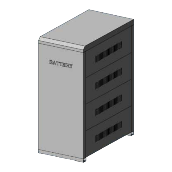
Cabinet dimension of A20: 780mm×470mm×1520mm (D×W×H), including connecting wires,
air switch and wire holder. The cabinet can be mounted up to 20 pieces 65AH/12V
battery or 100AH/12V battery, each layer has 4 pieces and five layers in total. The
external appearance is shown as Figure 1.
Figure 1
Installation Steps:
1. Place the cabinet base, then plug the V-slot of the front and rear panel into the
flume of the base's two sides correspondingly. Shown as Figure 2.
Advertisement

Summary of Contents for MAK A20
- Page 1 A20 Vattery Cabinet USER MANUAL A20 Battery Cabinet Cabinet dimension of A20: 780mm×470mm×1520mm (D×W×H), including connecting wires, air switch and wire holder. The cabinet can be mounted up to 20 pieces 65AH/12V battery or 100AH/12V battery, each layer has 4 pieces and five layers in total. The external appearance is shown as Figure 1.
- Page 2 USER MANUAL www.mak-powersis.de A20 Battery Cabinet Figure 2 2. According to the accompanying wiring diagram and list, laying the batteries on the base of the battery cabinet, connecting the wires, locking the wires on battery poles. Shown as Figure3. Figure 3 3.
- Page 3 USER MANUAL www.mak-powersis.de A20 Battery Cabinet Figure 4 4. After installation is completed, checking all connections and voltage of battery are accurate. Then install right and left side panels. Shown as Figure 5. Figure 5 5. Cover the cabinet’s cover. The installation of battery cabinet is completed. Shown...
- Page 4 A20 Battery Cabinet Figure 6 Wiring Method: A20 battery cabinet is placed Five groups battery. First connect the each battery group(4PCS batteries each group)in series, then connect the five battery groups in series. Connect the anode and cathode wires to the leading-in terminal of air switch on the rear panel, connect two wires from leading-out terminal to wire holder.
- Page 5 Figure 7: Battery wires connecting sketch-map Notes: Don’t anti-connecting the cathode and anode of the battery, or else that will do damage to the battery or cause other accidents. A20 battery cabinet’s fittings. Shown as the following: Case parts Quantity...
- Page 6 USER MANUAL www.mak-powersis.de A20 Battery Cabinet Base Black 450mm Double-ended OL15.5-8 terminal Front panel Black 1800mm Double-ended OL15.5-8 terminal Rear panel Red 200mm Single-ended OL15.5-8 terminal Rack Red 300mm Single-ended OL15.5-8 terminal Side panel Cover Cover of Wire holder C45 bracket...