Table of Contents
Advertisement
Quick Links
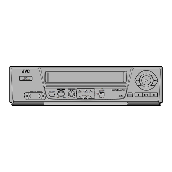
VIDEO CASSETTE PLAYER
HR - JP400K
HR - JP200A
STANDBY/ON
REMOTE CONTROL UNIT
VIDEO
TV/VCR
AUTO
- TRACKING +
- TV CH +
- VOLUME +
TV/VCR
STANDBY/ON
TV
VIDEO
The VCP illustrations appearing in this instruction manual are of the HR-JP400K.
Рисунки для видеомагнитофона, подаваемые в данной инструкции по
эксплуатации, относятся к модели HR-JP400K.
MIC
DIGITAL ECHO
1
MIC
2
SP/LP/EP
B.E.S.T POWER-ON
STANDBY / REC
MIN
MAX
0
10
AUDIO
SP/LP/EP
B.E.S.T POWER-ON
NTSC 3.58/4.43
PAL B / G, D / K MESECAM B / G, D / K RECORDING
STANDBY / REC
NTSC PLAYBACK ON PAL TV
INSTRUCTIONS
NTSC
PLAYBACK
ON PAL TV
LP / EP
NTSC
4.43
B.E.S.T.
PAL NTSC
NTSC 3.58
NTSC
PLAYBACK
ON PAL TV
LP / EP
NTSC
4.43
B.E.S.T.
PAL NTSC
NTSC 3.58
PAL NTSC
LPT0416-001A
Advertisement
Table of Contents

Summary of Contents for JVC HR-JP200A
- Page 1 VIDEO CASSETTE PLAYER HR - JP400K HR - JP200A STANDBY/ON SP/LP/EP REMOTE CONTROL UNIT VIDEO TV/VCR AUTO - TRACKING + - TV CH + - VOLUME + TV/VCR STANDBY/ON VIDEO AUDIO SP/LP/EP The VCP illustrations appearing in this instruction manual are of the HR-JP400K.
-
Page 2: Table Of Contents
Table of contents Thank you for purchasing this JVC video cassette player. To ensure optimum performance of this unit, please read this instruction manual thoroughly. Precautions ... 2 Controls ... 3 Terminals and wireless remote control ... 4 Connections ... 5 Setting the video channel ... -
Page 3: Controls
MIC volume control (HR-JP400K only) To adjust the microphone volume. SP / LP / EP button To select the recording tape speed. MIC input terminals (HR-JP400K only) & VIDEO/AUDIO IN terminals (HR-JP200A only) NTSC PLAYBACK ON PAL TV LP / EP NTSC 4.43... -
Page 4: Terminals And Wireless Remote Control
When using the remote control for operation of the video cassette player, make sure that it is pointed at the remote sensor window. You can also use the player’s remote control to operate a JVC television. Transmitting window TV/VCR (Player) button... -
Page 5: Connections
Make sure that the power to the video cassette player and TV is off before making the following connections. HR-JP400K HR-JP200A Connection A (basic) In order to use the video cassette player it must be connected between the antenna and the TV. -
Page 6: Setting The Video Channel
TV’s video/audio in terminals (connection B of the “Connections” section), set- ting the video channel is not necessary. In this case simply set the TV’s TV/VCR switch to VCR. Turn the video cassette player’s power on and load a pre-recorded video tape. -
Page 7: Playback
TV and video cassette player combination. Colour system output mode selec- REMOTE CONTROL UNIT VIDEO tion TV/VCR AUTO - TRACKING + To watch an NTSC tape, it will be necessary to select one of the following output modes. - TV CH +... -
Page 8: Playback Features
Playback features Slow motion playback Slow motion playback is 1/6 of the normal playback speed. The sound will be cut during slow motion playback. During playback: Press the Pause 8 button for 2 seconds. 7 Press the Play 3 button to return to the normal playback speed. -
Page 9: Recording
Insert a pre-recorded Karaoke tape. Press the PLAY 3 button. Adjust the MIC volume as necessary. Adjust the DIGITAL ECHO volume as necessary. REMOTE CONTROL UNIT VIDEO TV/VCR Start singing. AUTO - TRACKING + Note: - TV CH + Check that the power is off (standby mode) before plugging in... -
Page 10: Picture Sysytem
B.E.S.T . picture system The B.E.S.T. (Biconditional Equalized Signal Tracking) system checks the condition of the tape in use during recording and playback, and compensates to provide the highest-possible recording and playback pictures. The default setting for both recording and playback is ‘‘ON’’. Recording Insert a cassette with the record safety tab intact. -
Page 11: Editing
Receiver VIDEO CHANNEL Connect the player’s AUDIO and VIDEO OUT connectors to the recorder’s AUDIO and VIDEO IN connectors. Put the player in the Play mode. Put the recorder in the Record mode. HR-JP200A RF OUT 32(24) 40(27) AUDIO ANT.IN... -
Page 12: Troubleshooting
7 Dirt accumulated on the video heads after long periods of use causes such troubles. In this case, head cleaning requiring highly technical care is necessary. 7 For head cleaning, consult the nearest JVC dealer. Specifications Format ... VHS Standard Video recording system ... - Page 13 MEMO...


