Advertisement
Quick Links
ASSEMBLY INSTRUCTIONS
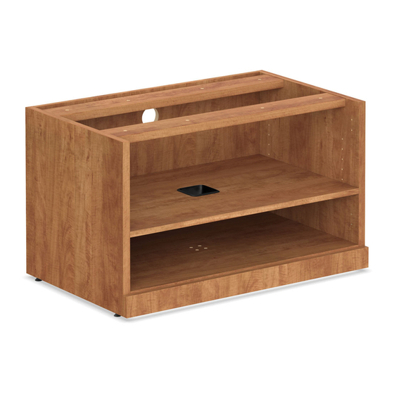
MODEL: PL 2013
Before assembly, please remove all parts from carton, verifying that you have the correct quantities, and read all the instructions.
IN THE CARTON:
1 1
2
Cam Lock
10 Pcs
9
JCBC Screw
M6 x 40mm = 4pcs
1
Washer = 8pcs
4
A
Bottom Panel
Last Updated: 02/2021
Last Updated: 3/2023
HARDWARE
3
4
Klix Cam
Housing Cap (Long)
Housing Cap (Short)
10 Pcs
8 Pcs
2 Pcs
12
10
11
M4 x 65
Allen-Key
Wire Cap
1 Pc
1 Pc
COMPONENTS
B
C
Adjustable Shelf-1
Back Panel
KLIX CAM INSTRUCTIONS
1
2
Insert the cam with the arrow
Line up Cam Lock,
pointing towards the hole in
turn clockwise.
F
E
B
OR
A
D
5
6
Adjustable
Iron Shelf Support
Glide
4 Pcs
4 Pcs
13
14
ALLEN CAP
Adjustable
Screw
SQUARE
Glide BIG
M10 x 70MM
PLATE 2 Pcs
1 Pc
4 Pcs
D
E
F
Front Rail
Side Panel x 2
Hanging Panel x 2
3
Insert the Cam Lock into Klix
Cam. Turn Klix Cam to lock.
the edge.
G
E
ASSEMBLY INSTRUCTIONS
MODEL NO. PL2013
8
7
Screw
6 Hole
#6 x 5/8"
L-Bracket
18 Pcs
3 Pcs
15
16
M10
Screw
Allen-Key
3.5X16MM
1 Pc
8 Pcs
G
Adjustable Shelf-2
OFFICESOURCE.COM
®
1 OF 2
Advertisement

Summary of Contents for OfficeSource PL2013
- Page 1 ASSEMBLY INSTRUCTIONS MODEL NO. PL2013 ASSEMBLY INSTRUCTIONS ® MODEL: PL 2013 Before assembly, please remove all parts from carton, verifying that you have the correct quantities, and read all the instructions. IN THE CARTON: HARDWARE Screw Adjustable 6 Hole Iron Shelf Support #6 x 5/8"...
- Page 2 ASSEMBLY INSTRUCTIONS ASSEMBLY INSTRUCTIONS MODEL NO. PL2013 ® MODEL: PL 2013 Before assembly, please remove all parts from carton, verifying that you have the correct quantities, and read all the instructions. INSTRUCTION: Attach the Bottom Panel (A) and Hanging Attach the another Side Panel (E) to Hanging Panel...


