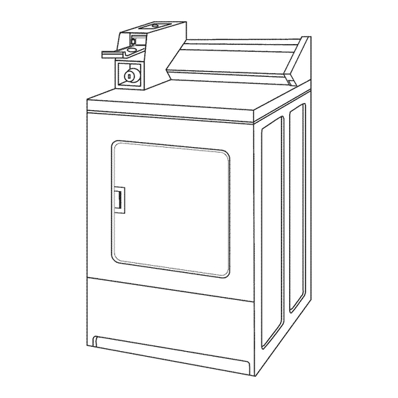
Summary of Contents for Whirlpool CGM2941TQ
- Page 1 INSTALLATION INSTRUCTIONS COMMERCIAL DRYER Gas (12(!-Volt,60-Hz) or Electric (12(}/24(}-Volt, 60-Hz) Table of Contents ............8563800 www,roper.com...
-
Page 2: Table Of Contents
TABLEOF CONTENTS DRYER SAFETY ................iNSTALLATiON REQUIREMENTS ..........Location Requirements .............. Tools and Parts ................Electrical Requirements ............Gas Supply Requirements ............Venting Requirements .............. iNSTALLATiON iNSTRUCTiONS - GAS DRYER ....10 install Coin Slide and Coin Box ..........10 Make Gas Connection .............. - Page 3 WARNING: For your safety, the information in this manual must be followed to minimize the risk of fire or explosion, or to prevent property damage, personal injury, or death. = Do not store or use gasoline or other flammable vapors and liquids in the vicinity of this or any other appliance.
-
Page 4: Installation Requirements
INSTALLATION REQUIREMENTS Gather the required tools and parts before starting installation. Read and follow the instructions provided with any tools listed here. Tools needed 8" or 10" pipe wrench 8" or 10" adjustable wrench Flat-blade screwdriver Phillips screwdriver Explosion Hazard [] Adjustable wrench that opens to 1"... - Page 5 Minimum Installation Clearances Product Dimensions 27" (68.6 cm) dryer 14" (35,6 ore) max, "_ 27" (68.6 cm) 15" Closet (88.1 cm)* door (88.6 cm) 37" o"(0cm) BACK VIEW (94cm) c::::::::::::::::::== 0" (O crn) __ I1 __1/26ore/ 13" , 4" (10.2 cm) Closet side view Recessed front view dia.
- Page 6 IMPORTANT: The dryer must be electrically grounded in accordance with local codes and ordinances or, in the absence of local codes, with the National Electrical Code, ANSI/NFPA 70, latest edition. The National Electric Code requires a 4-wire supply connection for homes built after 1996, dryer circuits involved in remodeling after 1996, and all mobile home installations.
-
Page 7: Location Requirements
i!!iii,, i:iiiiii (!;z iiF i!!:iiiieqxiiX', !! isesi: Gas Supply Line Recommended method Provide a gas supply line of rA" rigid (IPS) pipe to the dryer location. Pipe joint compounds that resist the action of LP gas must be used. Do not use TEFLON _ tape. With LP gas, piping or tubing size can be 1/2"minimum. -
Page 8: Gas Supply Requirements
For vent systems not covered by the vent specification chart, see kinking. Whirlpool Service Manual, "Exhausting Whirlpool Dryers," Part No. LIT603197, available from your Whirlpool parts distributor. Flexible metal vent must be fully extended and supported when the dryer is in its final position. Remove excess flexible metal vent... - Page 9 CFM of all the dryers in the room. Back-draft Damper Kits, Part No. 3391910, are available from your Whirlpool dealer and should be installed in each dryer's vent to prevent exhausted air from returning into the dryers and to keep the exhaust in balance within the main vent.
-
Page 10: Installation Instructions - Gasdryer
INSTALLATION INSTRUCTIONS - GASDRYER The console houses the factory-installed accumulator timer with Remove red cap from gas pipe. actuating arm and button. 2. Connect gas supply to dryer. Use pipe-joint compound resistant to the action of L.R gas for gas connections. If The timer installed is set to provide 45 minutes (4 pins) of drying flexible metal tubing is used, be certain there are no kinks. -
Page 11: Installation Instructions- Electric Dryer
4. Iftheburner does notignite and youcanfeel n oheat i nside thedryer, shut o ffdryer forfive minutes. Check t hatallsupply valve controls arein"ON" p osition a nd thattheelectrical cord isplugged i n.Repeat five-minute test. 5. Ifdrying t ime istoolong, m ake sure lintscreen i sclean. INSTALLATION INSTRUCTIONS - ELECTRICDRYER For dryers using coin slides, use adapter kit supplied with dryer. - Page 12 2. Remove hold-down screw and the terminal block cover. Assemble 3/4" UL-listed strain relief (UL marking on strain relief) into the hole below the terminal block opening. Tighten strain relief screws just enough to hold the two clamp sections together. Install power supply cord/cable through the strain relief.
- Page 13 Use this method where local codes permit connecting Power Supply Cord, neutral ground wire to neutral wire: A ....Three=wire electrical connection: 5. Loosen or remove the center terminal F-'__ block screw. F ..Connect the neutral wire (white or center) of the power supply cord to the center, silver-colored terminal screw of the ....
- Page 14 A. Extemat ground conductor screw B. Tab Fire Hazard C. Terminal block cover D. Hold-down screw Use 10 gauge solid copper wire. Use a UL listed strain relief. Install 3/4"conduit connector into the hole below the terminal Disconnect power before making electrical connections. block opening.
- Page 15 Direct Wire, Use this method where local codes permit Three=wire electrical connection: connecting neutral ground wire to neutral wire: 5. Loosen or remove the center terminal block screw. 6. Place the hooked end of the neutral wire (white or center) of the direct wire cable under the center screw of the terminal block (hook facing right).
-
Page 16: Changing To A 30-Or60-Minute Timingcam
CHANGING TO A 30-OR60-MINUTE TIMINGCAM Place new cam (hub side down) over clock shaft. Line up flat side of shaft with flat side of cam hole. Check that drive lug is in place. Electrical Shock Hazard Disconnect power hefore making cam changes. Failure to follow these instructions can result in death or electrical shock.


