Fujitsu MB91360 SERIES User Manual
Starterkit adapter
Hide thumbs
Also See for MB91360 SERIES:
- User manual (43 pages) ,
- Application note (35 pages) ,
- User manual (20 pages)
Table of Contents
Advertisement
Quick Links
Download this manual
See also:
User Manual
Advertisement
Table of Contents

Summary of Contents for Fujitsu MB91360 SERIES
-
Page 1: User Guide
Fujitsu Microelectronics Europe FMEMCU- UG-910002-15 User Guide MB91360 SERIES STARTERKIT ADAPTER STARTERKITMB91360-ADA120 USER GUIDE... -
Page 2: Revision History
File compression settings changed 17.07.01 Version 1.2 Corrections 31.10.02 Version 1.3, MST New format, MB91F365G/F366G series added 22/01/2003 Version 1.4 Typos corrected 06/02/2003 Version 1.5, MST Typos corrected This document contains 17 pages. UG-910002-15 - 2 - © Fujitsu Microelectronics Europe GmbH... -
Page 3: Warranty And Disclaimer
Product or parts thereof, if the Product is returned to Fujitsu Microelectronics Europe GmbH in original packing and without further defects resulting from the customer´s use or the transport. -
Page 4: Table Of Contents
1 INTERFACING THE MB91360 STARTER KIT TO THE STARTERKITMB91360-ADA120 AND PROBE CABLE....................... 6 2 APPENDIX ........................8 Pin comparision....................... 8 Figures ........................15 3 RELATED PRODUCTS ....................16 4 INFORMATION IN THE WWW..................17 UG-910002-15 - 4 - © Fujitsu Microelectronics Europe GmbH... -
Page 5: Introduction
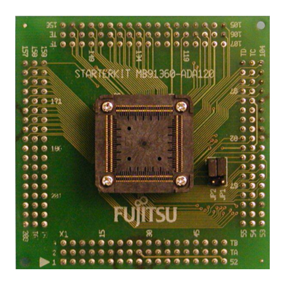
The Starterkit91360 is the Evaluation board for MB91360G series. It is equipped with MB91F362G series (208-pin). When using a 120-pin derivate (MB91F365G/F366G/F367G/F368G) the adapter board STARTERKITMB91360-ADA120 is mapping the pins to the functions on the Starterkit91360. © Fujitsu Microelectronics Europe GmbH - 5 - UG-910002-15... -
Page 6: Interfacing The Mb91360 Starter Kit To The Starterkitmb91360-Ada120 And Probe Cable
90° compared to the MB91FV360G. Also included is a pin cross-reference between the MB91FV360, MB91F365/6 and MB91F367/8. The following diagram shows the starter kit assembled with the STARTERKITMB91360- ADA120 Adapter board and probe cable. UG-910002-15 - 6 - © Fujitsu Microelectronics Europe GmbH... - Page 7 Chapter 1 Interfacing the MB91360 Starter Kit to the STARTERKITMB91360-ADA120 and probe Cable Figure 1 Diagram showing how to connect the STARTERKITMB91360-ADA120 Adapter board and Probe Cable to the MB91360 Starter Kit © Fujitsu Microelectronics Europe GmbH - 7 - UG-910002-15...
-
Page 8: Appendix
JP16 JP16 JP20 JP20 AVRH AVCC AVSS JP16 JP16 JP16 JP16 JP16 JP16 JP16 JP16 JP16 DA0: (MB91F365G) X0A: (MB91F366G) JP16 N .C. (MB91F367G) X0A: (MB91F368G) DA1: (MB91F365G) JP16 X1A: (MB91F366G) UG-910002-15 - 8 - © Fujitsu Microelectronics Europe GmbH... - Page 9 AH/BOOT TESTX CPUTESTX MONCLK INT0 JP20 INT1 JP20 INT2 JP20 INT3 JP20 INT4 JP20 INT5 JP20 INT6 JP20 INT7 JP20 VCC3/C JP20 JP20 JP20 JP20 OUT0 JP20 OUT1 JP20 INITX JP25 © Fujitsu Microelectronics Europe GmbH - 9 - UG-910002-15...
- Page 10 OCPA0 JP15 OCPA1 JP15 OCPA2 JP15 OCPA3 JP15 OCPA4 JP15 OCPA5 JP15 OCPA6 JP15 OCPA7 JP15 JP14 JP14 JP14 JP14 SIN0 JP14 SOT0 JP14 SIN1 JP14 SOT1 JP14 AN10 AN11 AN12 UG-910002-15 - 10 - © Fujitsu Microelectronics Europe GmbH...
- Page 11 PWM1M0 JP15 PWM2P0 JP15 PWM2M0 JP15 HVDD PWM1P1 JP15 PWM1M1 JP15 PWM2P1 JP15 PWM2M1 JP15 HVSS PWM1P2 JP15 PWM1M2 JP15 PWM2P2 JP15 PWM2M2 JP15 HVDD PWM1P3 JP15 PWM1M3 JP15 PWM2P3 JP15 © Fujitsu Microelectronics Europe GmbH - 11 - UG-910002-15...
- Page 12 LED1 LED2 LED3 JP25 JP25 JP25 JP25 JP25 JP25 JP25 JP25 JP25 JP25 JP25 JP25 JP25 JP25 JP25 JP25 JP25 JP25 JP25 JP25 JP25 JP25 AN14 AN15 JP25 BGRNTX JP25 JP25 UG-910002-15 - 12 - © Fujitsu Microelectronics Europe GmbH...
- Page 13 CS5X JP25 CS6X JP25 JP24 JP24 JP24 JP24 JP24 JP24 JP24 JP24 JP24 JP24 JP24 JP24 JP24 JP24 JP24 JP24 JP24 JP24 JP24 JP24 JP24 JP24 JP24 JP24 JP24 JP24 JP24 © Fujitsu Microelectronics Europe GmbH - 13 - UG-910002-15...
- Page 14 DEOP0 JP25 DREQ JP25 HSTX LTESTX OUT2 JP20 OUT3 JP20 JP25 JP25 JP14 SELCLK SIN2 JP14 SOT2 JP14 JP14 VDD35 VDD35 VDD35 VDD35 VDD35 VDD35 VDD35 VDDI VDDI VDDI VDDI VDDX UG-910002-15 - 14 - © Fujitsu Microelectronics Europe GmbH...
-
Page 15: Figures
Figure 1 Diagram showing how to connect the MB91F367/8 Adapter board and Probe Cable to the MB90F360 Starter Kit................7 Figure 2: Table comparing Pin and functions for the MB91FV360 series, MB91F369 and MB91F367/8......................8 © Fujitsu Microelectronics Europe GmbH - 15 - UG-910002-15... -
Page 16: Related Products
STARTERKITMB91360-ADA120 Chapter 3 Related Products 3 Related Products < Starterkit91360 Evaluation board for MB91360 series < MB2197-01 Emulator debugger main unit < MB2197-10 DSU Probe Cable < MB2197-120 Adapter board for MB91FV360G Evaluation device < MB2197-127 Probe cable for 208-pin socket (MB91F362G) -
Page 17: Information In The Www
STARTERKITMB91360-ADA120 Chapter 4 Information in the WWW 4 Information in the WWW Information about FUJITSU MICROELECTRONICS Products can be found on the following Internet pages: Microcontrollers (8-, 16- and 32bit), Graphics Controllers Datasheets and Hardware Manuals, Support Tools (Hard- and Software) http://www.fme.gsdc.de/gsdc.htm...


