Table of Contents
Advertisement
Advertisement
Table of Contents

Summary of Contents for WARPP WS-200
- Page 1 DC INVERTER TIG WELDING MACHINE WS-200 INSTRUCTION MANUAL WARPP ENGINEERS PVT. LTD. B-1005, Western Edge II, Near Metro Mall, Off. Western Express Highway, Borivali (E), Mumbai-400 066. Tel: 91-22-28542272 /73/74. Fax: 91-22-28542275. Email:sales@warpp.co.in Web Site: www.warpp.co.in...
-
Page 2: Table Of Contents
CONTENTS 1. Contents ····································································································································································· 1 2. Safety warning ··························································································································································· 2 3. Machine description ················································································································································· 3 4. Technical parameters table ······································································································································ 4 5. Installation instruction ············································································································································· 5 6. Panel function instruction ······································································································································· 6 7. Operation instruction ··············································································································································· 7 8. Notes or preventive measures ·································································································································· 8 9. -
Page 3: Safety Warning
SAFETY WARNING On the process of welding or cutting, there will be possibility of injury, so please take protection into consideration during operation. For more details please review the Operator Safety Guide, which complies with the preventive requirements of the manufacturer. Electric shock——May lead to death !... -
Page 4: Machine Description
MACHINE DESCRIPTION Welding machine is a rectifier adopting the most advanced inverter technology. The development of welding equipment benefits from the appearance of the inverter power supply theory and components. Inverter arc welding power source utilizes high-power component MOSFET to transfer 50/60Hz frequency up to 100 KHz, then reduce the voltage and commutate, and output high-power voltage via PWM technology. -
Page 5: Technical Parameters Table
TECHNICAL PARAMETERS TABLE Model WS 200 Parameters single phase Power voltage(V) AC220V±15% Frequency(Hz) 50/60 Rated input current(A) 30.8 Output current.(A) 10~200 Rated working volt.(V) No-load volt.(V) Force adjustment(A) —— Duty cycle(%) No-load loss (W) Arcing way Efficiency (%) Power factor 0.73 Insulation grade Housing protection grade... -
Page 6: Installation Instruction
INSTALLATION INSTRUCTION The machine is equipped with power voltage compensation equipment. When power voltage fluctuates between±15% of rated voltage, it still can work normally. When use long cable, in order to prevent voltage form going down, bigger section cable is suggested. If cable is too long, it may affect the performance of the power system. -
Page 7: Panel Function Instruction
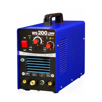
PANEL FUNCTION INSTRUCTION Front Panel 1. Power switch 2. Power indicator led 3. Abnormal indicator led 4. Welding current adjustment 5. MMA / TIG switch 6. Positive output terminal 7. Torch switch socket 8. Gas-electricity system output terminal 9. Negative output terminal ·... -
Page 8: Operation Instruction
OPERATION INSTRUCTION TIG Welding Description 1. Turn on the power switch of front panel, digital current meter is normal, fan begins to run. 2. Turn on argon switch, and adjust gas pressure to rated value.(refer to flow table). 3. Press switch of torch, electromagnetic valve is started. You will hear the sound of electricity-releasing HF sparkle and at the same time, argon gets out the torch. -
Page 9: Notes Or Preventive Measures
NOTES OR PREVENTIVE MEASURES 1. Environment 1) The machine can perform in environment where conditions are dry with a dampness level of max 90%. 2) Ambient temperature is between -10 to 40 degrees centigrade. 3) Avoid welding in sunshine or drippings. Do not let water enter the gas 4)... -
Page 10: Questions To Be Run Into During Welding
QUESTIONS TO BE RUN INTO DURING WELDING Fittings, welding materials, environment factor, supply powers maybe have something to do with welding. User must try to improve welding environment. A. Black welding spot: ——Welding spot is not prevented from oxidizing .User may check as following: 1. -
Page 11: Maintenance
MAINTENANCE WARNING: Power must be turned off for all checking and maintenance, before opening the housing, make sure the power plug is disconnected. Remove dust by dry and clean compressed air regularly, if welding machine is operated in environment where is polluted with smokes and polluted air, the machine need remove dust every month. -
Page 12: Notes Before Checking
NOTICE: In the period of guarantee maintenance, if user makes wrong check and repair for malfunction of welding/cutting machines without our permission, the free maintenance guarantee offered will be invalid TROUBLESHOOTING AND FAULT FINDING Notes: The following operations must be performed by qualified electricians with valid certifications. Before maintenance,please contact with us for professional suggestion. - Page 13 1. Maybe it is overheated protection, please close machine first, then turn on the machine again after abnormal indicator is out. 2. Maybe it is overheated protection, wait for 2-3 minutes (argon-arc welding does not has overheated protection function.) 3. Maybe inverter circuit is in fault, please pull up the supply power plug of main transformer which is on MOS board (VH-07 insert which is near the fan) then open the machine again.
- Page 14 SPARE PART LIST OF WS-200 DESCRIPTION PART CODE TOP PCB PCB-WS200T MIDDLE PCB PCB-WS200M BOTTOM PCB PCB-WS200B ON/OFF SWITCH PSW003 POTENTIOMETER FOR POT003 CURRENT SETTING (1K) KNOB FOR POT003 KNOB003 OUT PUT CONNECTOR CABLE FASTPLUG001-CM SIDE OUT PUT CONNECTOR FASTPLUG001...


