Sign In
Upload
Manuals
Brands
3M Manuals
Measuring Instruments
SP-SE-2-1/3
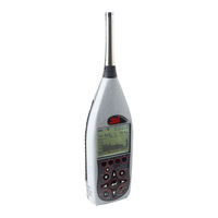
User Manuals: 3M SP-SE-2-1/3 Sound Level Meter
Manuals and User Guides for 3M SP-SE-2-1/3 Sound Level Meter. We have
1
3M SP-SE-2-1/3 Sound Level Meter manual available for free PDF download: User Manual
3M SP-SE-2-1/3 User Manual (168 pages)
Sound Level Meter. SoundPro SE series; SoundPro DL series
Brand:
3M
| Category:
Measuring Instruments
| Size: 1.89 MB
Table of Contents
Table of Contents
3
Figures
14
Introduction
14
Models and Options
14
Figure 1-1: Soundpro Models SE and DL and Option 1 and Option 2
14
Frequency Resolution
15
Figure 1-2: Octave Bands
15
Figure 1-3: Third Octave Bands
16
Table 1-1: Acoustical Range Bands
17
Analysis Type
18
Octave Bands
15
Naming Bands
16
Third -Octave Bands
16
Logging Explained
18
Physical Characteristics
18
The Display
18
Hardware Interfaces
19
Memory Card Slot
19
USB Port
19
Hardware Interface Panel
19
AC/DC Port
20
Power Jack
20
Auxiliary Port
20
The Unit Information Screen
21
Information Screen
21
Screen Contents
21
Detection Management Software DMS
22
DMS Start Page
22
Identify Soundpro Equipment
24
Installing the Preamp
25
Getting Started
24
Checking the Equipment
24
Figure 2-2: Soundpro & Preamp
25
Class/Type 1 and Class/Type 2 Instrument
26
Windscreen
26
Microphone and Accessories
25
Figure 2-3: Soundpro with Microphone and Windscreen
26
Providing Power
27
Installing Batteries
27
Battery Power Explained
28
Checking or Changing Type
28
Figure 2-4 : Installing Batteries
28
Battery Check Screen
28
Figure 2-6: Selecting Setup in the Start Screen
29
Using Power Supply or Auto Adapter
30
Selecting Setup in the Start Screen
29
Figure 2-7: Selecting Battery Type in Battery Check Screen
29
Figure 2-8: Attaching the Charger Adapter with the Plug Adapter
30
Figure 2-9: Base (or Bottom) of Soundpro
30
Turning on
31
Start Screen and the Keypad
31
Figure 2-10: Soundpro SE/DL Start Screen and Keypad
31
Soundpro Functionality
32
The Keypad Explained
32
Table 2-1: Keypad Explained
32
Indicators Explained
33
Table 2-2: Screen Indicators
33
Navigating
34
Turning off
34
Basic Setups
36
Table 3-1: Required Microphone Settings
36
Changing Microphone Settings
37
Microphone Settings (Signal Input Screen)
37
Time and Date
38
Time and Date Settings
38
Figure 3-3: Measurement Type and Start Screen
39
Figure 3-4: Meter 1 and Meter 2 Parameters
40
Measurement Setup (for Community Noise)
41
Measurement Type (SLM, 1/1, 1/3, STI-PA, RT60)
39
Meter 1/Meter 2 Parameters (I.e. Response Time, Weighting)
40
Measures Screen for Community Noise Settings
41
Table 3-2: Measures Screen Explained
42
C-A Measurement Settings
43
C-A Measurement Settings for Meter 1 and Meter 2
43
Logging
44
Logging Options
44
Exceedance Level
44
Filters
44
Logging Interval
44
Logged Data Chart Example
44
Setting Logging Options
45
Logging Screen Explained
45
Setting up Display Options
46
Figure 3-9: Display Setup Screen
46
Figure 3-10: Language Screen
47
Figure 3-11: Backlight Setting
48
Contrast
49
Backlight
48
Language
47
Advanced Setups
50
Setting up Auto-Run
51
Date Setting
51
Auto-Run
51
Figure 4-1: Auto-Run with Date Selected
51
Days of Week Setting
53
Figure 4-3: Example of Setting up Auto-Run (QSP-II)
54
Figure 4-2: Setting Date Parameters for Auto-Run #1
54
Day of the Week (DOW) Setup
54
Auto-Run Shutdown Screen
55
Auto-Run Shutdown Screen Explained
55
Figure 4-5: Auto-Run Shutdown Screen
56
Timed Run Setting
56
Timed Run Setup Screen
56
Level-Triggered Auto-On Setting
57
Level-Triggered Screen
57
Table 4-1: Level Triggered Auto-On Settings Explained
58
Locking Setup or Run Mode
59
Setting Secure Run or Secure Setup (Locking)
59
About Secure Run
59
About Secure Setup
59
Figure 4-8: Secure/Lock Option
60
Secure/Lock Screen
60
Adding Code for Secure/Lock Screen
61
Secure/Lock Run Prompt
61
Disabling Secure Run or Secure Setup (Unlocking)
62
Secure Code Backup Number
62
Secure/Lock Setup Prompt
62
Digital Outputs/Triggering
63
Tracking Runs
63
Digital Outputs and SPL
64
Communications
64
Figure 4-14: Qsp/Serial
65
Figure 4-13: Digital-Out Screen
65
Qsp/Serial
65
Mass Storage
65
Figure 4-15: Mass Storage
66
Viewing Real-Time Measurements Remotely
66
Log to Port
66
Gps
67
GPS Display
67
GPS Explained
67
Comm-Set Screen for GPS Data
67
Figure 4-18: Viewing GPS Coordinates in COMM-Set Screen
68
Preparing to Measure & Running
70
Table 5-1: Measurement Notations
70
Virtual Meters
70
Meter 1/Meter 2 Explained
70
Measurement Notation (IEC/ISO)
70
Overview of Running a Session/Study
71
Preparing to Measure
72
Sessions and Studies
72
Table 5-2: Sessions and Studies Explained
72
Measurement Range
73
Calibrate
74
Calibration Screen
74
Pre-Calibration
74
Post-Calibration
74
Performing a Calibration
75
Figure 5-2: Attaching Calibrator to Soundpro
76
Figure 5-1: Bar Chart Screen (A) and Filtered Bar Chart (B)
76
Figure 4-18: Viewing GPS Coordinates in COMM-Set Screen
76
Setting Pre-Cal Screen
76
Calibration History Screen
76
Running a Session/Study
77
Post-Calibrate History Screen
77
Bar Chart Screen in Run Mode
77
Measurement Navigation
78
Using Softkeys in Measurement Screens
78
Table 5-3: Measurement Screens Explained
78
Analysis Type, Time Response and Weighting
79
Changing Displayed Measurement
79
Measurement Screen Icons
80
Descriptor Types
80
Table 5-4: Measurement Icons and Screen Descriptors Explained
80
Figure 5-8: Example Measurement Icons & Descriptors
81
Figure 5-7: Selecting Measurements with Lookup Softkey
81
Measurement Screens
81
Bar Chart and Filtered Bar Chart
81
Bar Chart Screen and Filtered Bar Chart Screen
81
Community Noise Screen
82
Figure 5-10: Community Noise Screen
83
Dosimetry Screen
83
Dosimetry Measurements
83
Tabulation Screens
84
1/1 and 1/3 Octave Analysis Measurement Results
84
Figure 5-12: Tabulation Screen for Octave Filtering
85
Figure 5-11: Dosimetry Screen
85
Time History/Back-Erase Screen
85
Back-Erasing
85
Results of Back-Erasing
86
Figure 5-13: Back-Erasing
87
Time Log Screen
87
Stopping a Session
88
Stopping and Pausing
88
RT60, Curves, and STI-PA
90
Additional Options
90
Reverberation
90
Figure 5-15: Stopping and Pausing
91
Reverberation (RT60) Methods
91
Reverberation Time (RT60)
91
Reverb Time
91
Interrupted Noise
92
Impulse Noise
92
Interrupted Noise Example
92
Reverberation Options
93
Table 6-1: Reverb Time Set-Up Options
93
Setting up Reverberation
94
Reverb Time Setup Screen
94
Running Reverberation Test
95
Reverberation Results
96
RT60 Summary Screen
97
Viewing RT60 Values of each Band
97
Deleting RT60 Value in a Filtered Band
97
RT60 Bar Chart Screen
97
Decay Curve Screen
98
Figure 6-6: Decay Curve Screen
99
Table 6-2: Tabular RT60 Field Explanation
99
Tabular RT60 Screen
99
Tabular Octave Filtering RT Screen
99
Curves
100
Captured Curves
100
Captured Curve Applications
100
Setting up Captured Curves
101
Selecting Measurement Type for Curves
101
Figure 6-9: Captured Curves and Survey Mode
102
Running Captured Curves
103
Figure 6-10: Selecting 1/1 or 1/3 for Measurement Type
104
Criterion Curve Families
104
Types of Criterion Curves
104
Capturing a Curve (CAP-1)
104
Setting up Criterion Curves
105
Curves Setup Screen Example
106
Audiometric Background Curves
107
Setting up Audiometric Background Curves
107
1/1 or 1/3 Octave Measurement Type for Audiometric Testing
107
Selecting Measurement Type for Curves
108
Figure 6-16: Audiometric Booth Setup in the Curves Screen
108
Running and Viewing Curves
109
Curve Measurements and Results
109
Figure 6-17: Curve Results
110
Speech Intelligibility
111
STI-PA Testing
111
Zones
111
Selecting STI Scale or CIS Scale
111
STI Scale
112
Common Intelligibility Scale (CIS)
112
When to Take STI-PA Readings
112
Conducting a STI-PA Test (Overview of Steps)
113
STI-PA Setup
113
Measurement Type Selection (STIPA)
114
Table 6-3: Measures Setup Screen Parameters Explained
114
Conducting a Level Setup (for STI-PA)
116
Running a Speech Intelligibility Study
116
Figure 6-19: STI-PA Setup Screen
117
Figure 6-20: Level Set-Up and Average Decibel Level
117
STI-PA Results Screens
117
STI-PA Measurement and Scale Results Screen
117
STI-PA Measurement (Scale Results) Screen
117
STI-PA Modulation Screen
118
STI-PA Modulation Envelope Screen
119
Applying Captured Curves for STI-PA Testing
121
Figure 6-23: STI-PA Modulation Envelope Screen
121
Captured Curves/Background Noise
121
Viewing Past Measurements
124
Files
124
File Directories
124
File Directory Screen Explained
125
Viewing Past Sessions/Studies (Review Mode)
125
Figure 6-27: Post CAP-1 Applied During STI-PA Test
125
File Screen
125
Figure 7-4: Data File Screen
127
Figure 7-5: Selecting Past Study Data (Review Mode)
129
Session Directory
129
Figure 7-2: Start Menu Screen
127
Figure 7-3: File Menu Screen
127
Loading and Deleting Files
128
Figure 7-6: Viewing Past Data Example
129
Loading and Deleting Files
129
Navigating in a Session/Config. Directory
130
Naming and Renaming Files
130
Configuration Directory
131
Saving (& Naming) Setup File (Config. File)
131
Figure 7-8: Examples of Directory Screens
132
Figure 7-10: Saving/Creating Setup File (Config. File)
132
Viewing, Loading, Deleting Setup Files (Config.)
132
Viewing, Loading, Deleting Setup Files
132
Memory Card
133
Compatibility
133
Formatting a Card with the Soundpro
133
Communicating
134
Communicating with a PC
134
Using Detection Management Software DMS
134
Using an External Card Reader
134
Working with Measurement Data in DMS
134
DMS and Working with Soundpro Data
135
AC/DC Output
136
AC Output
136
DC Output
136
Table 8-1: AC Output
136
Specifications
138
Conformance to Standards
138
Acoustics
138
EMC Emissions and Immunity
138
Mechanical Characteristics
138
Electrical Characteristics
139
Power Sources
139
Internal Power
139
External Power
140
Preamplifier (Removable)
140
Meters
140
Bandwidth
140
Octave Filters (Optional)
141
Third-Octave Filters (Optional)
141
Instrument Noise
141
Environmental Effects
141
Temperature
141
Humidity
142
User Interface
142
Display
142
Keypad
142
Languages
142
Input/Output
142
Microphones
142
AC/DC Outputs
143
Communications Ports
144
Measurements
144
Types
144
Ranges
144
Measurement Parameters
144
Other
145
Calibration
145
Studies and Sessions
145
Special Features
145
Security
145
Back-Erase
146
Logging (Optional)
146
Part Numbers
146
Replacement Parts
146
Optional Parts
147
Figure A-1: Pinout for the AC/DC Output Jack
148
Port Pinouts
148
AC/DC Jack
148
Auxiliary Connector
148
Block Diagram for Soundpro
149
Glossary of Terms
150
Dynamic Range
151
Customer Service
162
Contacting 3M
162
Warranty
163
Advertisement
Advertisement
Related Products
3M SP-SE-2-1/1
3M SP-SE-2
3M SP-SE-1
3M SP-SE-1-1/1
3M SP-SE-1-1/3
3M SP-DL-2
3M SP-DL-2-1/3
3M SP-DL-1
3M SP-DL-1-1/1
3M SP-DL-1-1/3
3M Categories
Projector
Respiratory Product
Safety Equipment
Water Filtration Systems
Headsets
More 3M Manuals
Login
Sign In
OR
Sign in with Facebook
Sign in with Google
Upload manual
Upload from disk
Upload from URL