Sign In
Upload
Manuals
Brands
Brother Manuals
All in One Printer
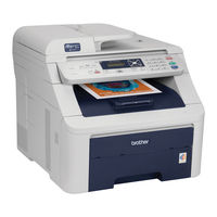
MFC-9325CN
Brother MFC-9325CN Manuals
Manuals and User Guides for Brother MFC-9325CN. We have
1
Brother MFC-9325CN manual available for free PDF download: Service Manual
Brother MFC-9325CN Service Manual (598 pages)
Color FAX/MFC
Brand:
Brother
| Category:
All in One Printer
| Size: 22.96 MB
Table of Contents
Chapter 1 Specifications
12
Service Manual
1
CHAPTER 6 Required after Parts Replacement
3
Safety Information
7
Table of Contents
12
Components
13
Specifications List
14
General
14
Configuration Tool
19
Network Connectivity
23
Wireless Network
25
Service Information
29
Consumables
30
Paper
31
Media Specifications
31
Paper Handling
31
Type and Size of Paper
32
Printable Area
33
Print Speeds with Various Settings
41
Telephone
42
Fax
44
List/Report
48
Copy
49
Scanner
50
USB Direct Interface
52
CHAPTER 2 Theory of Operation
53
Chapter 2 Theory of Operation
54
General Block Diagram
56
Electronics General Block Diagram
57
Mechanics
58
Cross-Section Drawing
58
Printer Part
58
Scanner Mechanism
60
Document Scanner Unit
61
ADF Unit
63
Paper Feeding
65
Plate-Up Function of the Paper Tray
66
Paper Supply
67
Paper Registration
68
Paper Eject
69
Paper Supply from Manual Feed Slot and Paper Eject from Back
70
Toner Cartridge
71
Life of Toner Cartridge
71
Type of Toner Cartridge
71
Method of Detecting Toner Life
72
Relationship between Toner Amount and Life of Toner Cartridge in Number of Rotations of Develop Roller
72
New Toner Detection
74
Method of Counting the Number of Toner Replacements
76
Principle of Color Overlapping
77
Basic Printing Principle
78
Charging
79
Exposure
80
Development
81
Transfer
82
Fusing
83
Toner Cleaning
84
Adjustment of Color Density
89
Adjustment of Color Registration
89
Color Registration Error in Sub/Main Scanning Direction
89
Chapter 3 Error Indication and Troubleshooting
91
Precautions
93
Components
94
Initial Check
95
Operating Environment
95
Power Supply
95
Error Indications
97
Error Codes
97
Error Messages
100
Error Cause and Remedy
103
Error Code 25
108
Error Code 26
108
Error Code 29
108
Paper Feeding Problems
149
No Feeding
149
Double Feeding
150
Paper Jam
150
Dirt on Paper
151
Wrinkles on Paper
152
Curl of Paper
152
Print Image Defect from Pc/Usb/Fax Reception Troubleshooting
153
Image Defect Examples
153
Pitch Indicated in Roller Image
154
Troubleshooting Image Defect
154
One Color Is Light
155
Faulty Registration
156
Poor Fixing
158
Image Distortion
159
All One Color
160
Vertical Streaks
162
Horizontal Stripes
164
Faint Print
166
One Color Band
172
Horizontal Lines
173
Color Misregistration
174
Hollow Print
177
Software Setting Problems
178
Cannot Print Data
178
Network Problems
179
Cannot Make a Print through Network Connection
179
Troubleshooting of the Communications Errors
180
Definition of Error Codes on the Communications List
180
Troubleshooting of the Control Panel Cover Assy
186
Nothing Is Displayed on the LCD
186
The Control Panel Cover ASSY Does Not Work
187
Troubleshooting of Fax Functions
188
FAX Can't Send It
188
Speed Dialing and One-Touch Dialing Can't be Used
189
FAX Can't be Received
189
No Bell Ring
190
Speaker Is Silent During On-Hook Dialing
190
Dialing Function Does Not Switch between "Tone" and "Pulse
191
Document Feeding Problems
192
No Feeding
192
Double Feeding
192
Paper Jam
193
Wrinkles
194
Scanning Image Defect Troubleshooting
195
Image Defect Examples
195
Troubleshooting Image Defect
195
Others Problems
198
The Machine Is Not Turned On, or the LCD Indication Does Not Appear
198
The Fan Does Not Work
199
Pickup Function of Paper Tray Does Not Work
199
The New Toner Is Not Detected
200
Printing from Macintosh Applications Fails
200
USB Direct Printing Does Not Work
200
(USB Direct Interface Model Only)
200
Periodical Maintenance
201
Chapter 4 Periodical Maintenance
202
Consumable Parts
203
Safety Precautions
203
Periodical Maintenance Parts
205
Procedures to Replace Periodical Maintenance Parts
206
Fuser Unit
207
Installing Procedure
213
Paper Feeding Kit
219
CHAPTER 5 Disassembly and Assembly
224
Chapter 5 Disassembly and Assembly
225
Safety Precautions
228
Packing
229
Screw Torque List
230
Lubrication
233
Overview of Gears
235
Harness Routing
239
Toner Led Pcb Assy
247
Back Cover Sensor
249
Panel Unit
253
Disassembly Flow
257
Disassembly Procedure
259
Cord Hook
260
EXT Cap
261
Roller Holder ASSY
262
Separation Pad ASSY
264
Back Cover/Back Cover Stopper L/R
266
Fuser Cover
269
Paper Eject Front Actuator
270
Fuser Unit
272
Side Cover L Assy/Access Cover
276
Side Cover R ASSY
279
Pull Arm L/Pull Arm R/Pull Arm Spring
281
Hinge ASSY L
285
Hinge R/Hinge R Support/Hinge Base
287
ADF Cover ASSY
288
Gear Cover
289
Separation Roller Shaft ASSY
290
Upper Document Chute ASSY
291
Separation Rubber ASSY
292
Paper Feed Roller ASSY
293
Ejection Roller ASSY
294
ADF Sensor PCB ASSY
295
Drive Frame ASSY
298
Paper Stack Lever
302
Document Hold ASSY
303
Control Panel Cover ASSY
304
Document Scanner Unit
305
Panel PCB ASSY
306
Rubber Key L/R
307
LCD/LCD Cover
308
NCU PCB ASSY (NCU Model Only)
310
Battery ASSY
311
Pull Arm Guide
312
Top Dress Cover L/R
313
FB Lock Lever L/R
314
Joint Cover Lock Spring/Joint Cover Lock Lever
317
Wireless LAN PCB ASSY (Wireless LAN Model Only)
318
USB Direct Interface Relay PCB ASSY (USB Direct Interface Model Only)
321
Speaker Unit/Front Cover Top Base
325
Front Cover
327
Manual Feed Slot ASSY
328
TC Arm Spring
329
Arm Guide L Cover
333
Joint Cover Sub ASSY
334
Inner Chute ASSY 2
337
TC Release Lever
338
Paper Stack Lever ASSY
344
FFC Harness:main-LED CTL
345
LED Power Relay PCB ASSY
348
LED Head Control PCB ASSY
349
LED Assy/Holder Hook
351
Z Spring L/Z Spring R
360
Develop Release Motor ASSY
362
Main PCB ASSY
364
Engine PCB ASSY
365
Main PCB Insulation Sheet/Engine Insulation Sheet
366
Main PCB Shield Plate
367
Engine Shield Plate
368
Registration Mark Relay PCB ASSY
369
Drum Develop Drive Unit
370
Develop Drive Motor
375
Paper Feed Motor ASSY
376
Paper Feed Unit
378
Registration Front/Rear Sensor PCB ASSY
381
Manual Sensor PCB ASSY
383
Pick-Up Sector Gear Spring/Friction Spring
384
PF Registration Solenoid
385
Pick-Up Solenoid/Pick-Up Solenoid Lever Spring
389
Fuser/Eject Drive Motor
391
Fuser/Eject Drive Motor Sensor PCB ASSY
392
Top Cover Arm R
393
Top Cover Arm L
394
Air Filter Holder Assy/Ozone Filter
395
Paper Eject Rear Actuator/Paper Eject Rear Actuator Spring/Paper Eject Rear Actuator Top
398
Eject Rear Sensor PCB ASSY
401
Eject Front Sensor PCB ASSY
402
Toner/New Sensor PCB ASSY
403
Belt Drive ASSY
404
Drum Motor Origin Sensor PCB ASSY
405
LV Fan ASSY
406
Main Fan ASSY
408
Low-Voltage Power Supply PCB ASSY
409
Registration Sensor Holder ASSY
415
High-Voltage Power Supply PCB ASSY
416
HVPS Control PCB ASSY
422
Waste Toner Sensor
423
Develop Release Sensor PCB ASSY
426
Belt Cleaner Spring
427
TR Head Spring
431
Side Frame R
433
Toner LED PCB ASSY/LED Holder
436
LM Hook B/LM Hook C/Hook Spring BC10
437
Chapter 6 Adjustments and Updating of Settings, Required after Parts Replacement
441
If You Replace the Main Pcb
442
Checking Firmware Version
448
Rewriting the Firmware (Main Firmware, Sub Firmware (PCL/PS))
448
Rewriting the Firmware Using Computer
448
Rewriting the Firmware Using USB Flash Memory (USB Direct Interface Model Only)
450
Initialization of EEPROM of Main PCB (Maintenance Mode: Code 01)
452
Setting by Country (Maintenance Mode: Code 74)
452
Setting the Serial Number
452
Acquiring MAC Address (Ethernet Address) from Wireless LAN PCB (Wireless LAN Model Only)
454
Acquiring White Level Data (Maintenance Mode: Code 55)
454
Performing Operational Check of Operation Panel Buttons (Maintenance Mode: Code 13)
454
Performing the Adjustment of Color Registration (Maintenance Mode: Code 66)
454
Performing the Developing Bias Voltage Correction (Maintenance Mode: Code 83)
454
Sensitivity Adjustment of Density Sensor (Maintenance Mode: Code 72)
454
If You Replace the Document Scanner Unit
455
Acquiring White Level Data and Setting CIS Scanner Area
455
CHAPTER 7 Service Functions
456
If You Replace the Registration Sensor Holder Assy
455
Sensitivity Adjustment of Density Sensor (Maintenance Mode: Code 72)
455
If You Replace the Wireless Lan Pcb (Wireless Lan Model Only)
455
Acquiring MAC Address (Ethernet Address) from Main PCB
455
Chapter 7 Service Functions
457
Maintenance Mode
459
How to Enter the Maintenance Mode
459
How to Enter the End User-Accessible Maintenance Mode
459
List of Maintenance-Mode Functions
460
Detailed Description of Maintenance-Mode Functions
461
EEPROM Parameter Initialization (Function Code 01, 91)
461
Printout of Scanning Compensation Data (Function Code 05)
462
ADF Performance Test (Function Code 08)
465
Placement of Scanner Unit in Position for Transportation (Function Code 06)
465
Monochrome Image Quality Test Pattern (Function Code 09)
466
Worker Switch (WSW) Setting and Printout (Function Code 10, 11)
467
Operating Procedure
469
Operational Check of LCD (Function Code 12)
471
Operational Check of Control Panel Button (Function Code 13)
472
Software Version Check (Function Code 25)
473
Operational Check of Sensors (Function Code 32)
474
Operational Procedure
474
Function Setting
478
PC Print Function (Function Code 43)
478
Not-Disclosed-To-Users Functions (Function Code 45)
481
EEPROM Customizing (User-Accessible) (Function Code 52)
485
Received Data Transfer Function (Function Code 53) (FAX Model Only)
486
Fine Adjustment of Scan Start/End Positions (Function Code 54)
488
Acquisition of White Level Data (Function Code 55)
489
Adjustment of Color Registration (Function Code 66)
490
Continuous Print Test (Function Code 67)
493
LED Test Pattern Print (Function Code 68)
495
Frame Pattern Print (Function Code 69)
497
Color Test Pattern (Function Code 71)
499
Sensitivity Adjustment of Density Sensor (Function Code 72)
501
Setting by Country (Function Code 74)
502
Sensitivity Adjustment of Registration Mark Sensor and Check of Belt Surface (Function Code 75)
504
Printout of Maintenance Information (Function Code 77)
506
Operational Check of Fans (Function Code 78)
507
Display of the Machine's Log (Function Code 80)
508
Error Code Indication (Function Code 82)
511
Developing Bias Voltage Correction (Function Code 83)
512
Counter Reset after Replacing the Fuser Unit and Paper Feeding Kit (Function Code 88)
513
Exit from Maintenance Mode (Function Code 99)
513
Function Code
513
Output of Transmission Log to the Telephone Line (Function Code 87)
513
Other Service Functions
514
Resetting the Periodical Maintenance Parts Life
514
Resetting the Life Counter of the Belt Unit
514
Resetting the Life Counter of the Fuser Unit
514
Resetting the Life Counter of the Drum Unit
515
Resetting the Life Counter of the Paper Feeding Kit
515
Develop Roller Counter Reset Function
516
How to Recover from Errors of the Fuser Unit
517
Circuit Diagrams
520
Wiring Diagram
531
Deletion of User Setting Information Etc
588
Screw Catalogue
593
Machine Specification
596
Paper Specification
596
Advertisement
Advertisement
Related Products
Brother MFC-9340CDN
Brother MFC-9320CN
Brother MFC-9750
Brother MFC9650 Series
Brother MFC-9420CN
Brother MFC-9450CDN
Brother MFC-9*970CDW
Brother MFC-99465CDN
Brother MFC 9760 - B/W Laser - All-in-One
Brother MFC 9600 - Laser Printer - 12 Ppm
Brother Categories
Sewing Machine
All in One Printer
Printer
Label Maker
Fax Machine
More Brother Manuals
Login
Sign In
OR
Sign in with Facebook
Sign in with Google
Upload manual
Upload from disk
Upload from URL