Sign In
Upload
Manuals
Brands
Hitachi Manuals
Air Conditioner
RAD25QH4
Hitachi RAD25QH4 Manuals
Manuals and User Guides for Hitachi RAD25QH4. We have
3
Hitachi RAD25QH4 manuals available for free PDF download: Service Manual, Instruction Manual
Hitachi RAD25QH4 Service Manual (294 pages)
Brand:
Hitachi
| Category:
Air Conditioner
| Size: 20.28 MB
Table of Contents
Specifications
1
Table of Contents
1
Service Manual
1
Safety During Repair Work
2
Working Standards for Preventing Breakage of Semiconductors
4
Object Parts
4
Items to be Observed in Handling
4
Conductive Container
4
Grounding of the Working Table
6
Grounding a Solder Iron
6
Caution
8
Specifications Table
10
Specification of Room Air Conditioner
12
Triple System Multi RAC Multizone 70H Cool/Heat Capacity Spec
14
Triple System Multi RAC RAM-70QH4 Indoor Units Combinations
18
Quadruple System Multi RAC Multizone 80H Cool/Heat Combinations
22
Quadruple System to be Able to Install
26
Features
30
Refrigerant Piping Materials
32
Thickness of Refrigerant Piping
32
Flare's Expansion Pipe
32
Flare Nut Dimensions
32
Servicing Tools
34
Servicing Work (Refrigerant Recharging)
36
Top and Bottom Air Blow System
38
Damper State in each Operation Mode
40
Damper Mechanism
42
Setting of Switches
44
High Static-Pressure Switch
44
How to Use
46
Safety Precaution
46
Multi-Air Conditioner
47
Names and Functions of each Part
47
Indoor Unit Indicators
47
Stopped Indoor Units
47
Indoor Unit Control Panel
48
How to Open or Close the Front Panel
48
Temporary Switch
48
Air Outlet Switch
48
Various Functions
49
Automatic Operation
49
Remote Controller
49
Auto Restart Control
49
Heating
50
Dehumidifying
50
Cooling Operation
51
Fan Operation
51
How to Set the Timer
52
How to Cancel Reservation
52
How to Set the Sleep Timer
53
Adjusting the Air Deflectors
53
How to Change the Batteries in the Remote Controller
54
How to Use the Air Conditioner Effectively
54
Maintenance
54
Air Filter
54
Capabilities
55
Timer Programming/Sleep Timer Operation
55
Circuit Breaker
56
How to Install and Remove the Front Panel
57
Cleaning the Front Panel
57
Maintenance at Beginning of Long off Period
57
Air Cleansing and Deodorizing Filters
58
Regular Inspection
59
Installation
74
Height Difference
74
Piping Length
74
Outdoor Unit Installation
76
Construction and Dimensional Diagram
78
Main Parts Component
86
Thermostat Specifications
86
Fan Motor Specifications
86
Compressor Motor Specifications
87
Wiring Diagram - Indoor Unit
88
Wiring Diagram - Outdoor Unit
90
Wiring Diagram of the Printed Wiring Board
94
Block Diagram
103
ASIC Mode
105
Fan Speed by Mode
107
Room Temperature Shift Value
109
Basic Cooling Operation Chart
113
Dehumidifying Chart
117
Cooling Defrost
117
Basic Heating Operation Chart
119
Heating Sleep Operation
121
Expansion Valves
123
Compressor Rotation Speed
123
Changing the Number of Units to be Operated
125
Defrosting Start / Release Request Judgement
127
Defection Process Diagram
127
Defrosting Start Conditions
129
Defrosting Stop Conditions
129
Outputs During Defrosting
129
During One-Cycle Heating Operation
129
During Two-Cycle Heating Operation
131
Auto Fresh Defrosting
135
Processing at Overheat Thermistor (OH) High Temperature
137
Restriction Start Conditions
137
When Two Units Are Operated for Heating
137
When One Unit Is Operated for Heating
139
Forced Cooling
141
Operation State of Forced Cooling
143
Refrigerating Cycle Diagram
145
Auto Swing Function
147
Description of Main Circuit Operation
149
Power Circuit Diagram
149
Reset Circuit Diagram
151
Timing Chart
151
Room Temperature Thermistor Circuit
153
Heat Exchanger Thermistor Circuit
153
Humidity Sensor Circuit
153
Fan Motor Drive Circuit
155
Damper Control
157
Monitor Function of Damper Limit SW
157
Damper Operation by Operating Modes
157
Main Operation ON/OFF (with Preheating)
157
Thermo Intermittence
159
Sleep Timer
159
Reversing Valve Defrost
159
Cooling Mode
161
Dash Operation (no Smell Prevention)
161
Damper Open Operation (Except Dash)
161
Main Circuit Operation Description
163
Reset Circuit
163
Receive Circuit
165
Buzzer Circuit
165
Auto Sweep Motor Circuit
167
Micro Computer Output Signals
167
Auto Sweep Motor Rotation
167
Heat Exchanger Temperature Thermistor Circuit
169
Initial Setting Circuit
171
Drain Pump Drive Circuit
171
Drain Pump Trial Run Switch
173
Float Switch
173
DC Fan Motor Drive Circuit
175
High Static-Pressure Switch (Full Duct Type and Semi Duct Type)
177
Power Supply Circuit
179
Functions of Main Parts
181
System Power Module (SPM)
181
Diode Stack
181
Smoothing Capacitor
181
Interface Circuit
185
Interface Circuit Diagram
187
Example of Checking
189
Power Module Circuit
191
Switching Order of Power Module
193
Power Module Circuit (U + Is ON, V - Is ON)
195
PWB Power Supply Circuit (Switching Power Circuit)
197
Indoor Unit 1
197
Indoor Unit 2
197
Indoor Unit 3
197
Switching Power Supply Circuit for Outdoor Control P.W.B.
199
Voltage Specification
199
Switching Power Supply Circuit for Indoor Unit
201
Overload Control Circuit (OVL Control Circuit)
205
Temperature Detection Circuit
207
Correspondence between each Thermistor Resistance and Temperature
209
LED Lighting Mode at the Thermistors Troubled
211
Power Factor Control Circuit
213
Boosting and Varying DC Voltage VD
215
Service Call Q & a
217
Cooling Mode
217
Dehumidifying Mode
217
Heating Mode
217
Fonctionnement Automatique
220
Disassembly and Reassembly
225
Air Filter Cleaning
225
Front Panel
225
Front Cover Removal/Attaching
227
Indicator PWB
227
Discharge Frame
229
Damper Motor-Damper Limit Switch
231
Negative Ion Generating Device
231
Fan Motor Tangential Air Flow Fan
233
Troubleshooting
237
Precautions for Checking
237
Discharging Capacitors
239
Inspecting External Electrical Parts
241
Inspection Method 1
243
Inspection Method 2
245
Inspection Method 3
251
Inspection Method 4
253
Example of Indoor P.W.B. Checking Method
255
How to Operate Using the Service Switch the Outdoor Unit
257
How to Operate the Outdoor Unit Independently
257
Lighting Mode of the Self-Diagnosis Lamp
259
Installation Position of Self-Diagnosis Lamp
259
Troubleshooting of the System Power Module
263
How to Check Power Module
265
Checking Power Module Using Tester
265
Troubleshooting When the Timer Lamp Blinks
267
Checking the Indoor Unit Electrical Parts
269
Power Does Not Come on (no Operation)
269
Only Indoor Fan Does Not Operate (Others Are Normal)
271
Indoor Fan Speed Does Not Change (Others Are Normal)
271
All Systems Stop after Operation Is Started
273
Exploded View
275
Parts List
276
Advertisement
Hitachi RAD25QH4 Service Manual (145 pages)
MULTIZONE 70/80H
Brand:
Hitachi
| Category:
Air Conditioner
| Size: 9.23 MB
Hitachi RAD25QH4 Instruction Manual (29 pages)
INDOOR UNITS/OUTDOOR UNIT
Brand:
Hitachi
| Category:
Air Conditioner
| Size: 3.19 MB
Advertisement
Advertisement
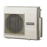
Related Products
Hitachi RAD-25NHA1
Hitachi RAD-25NHA2
Hitachi RAD-25NH5
Hitachi RAD-25RPA
Hitachi RAD-25NH4
Hitachi RAD-25NH7
Hitachi RAD-25NH7A
Hitachi MULTIZONE RAD-25RPE
Hitachi RAD-SH09QHLAE
Hitachi airHome RAD-DJ25QHAE
Hitachi Categories
Projector
Air Conditioner
Drill
Power Tool
TV
More Hitachi Manuals
Login
Sign In
OR
Sign in with Facebook
Sign in with Google
Upload manual
Upload from disk
Upload from URL