Sign In
Upload
Manuals
Brands
Honeywell Manuals
Control Unit
TC 4
Honeywell TC 4 Manuals
Manuals and User Guides for Honeywell TC 4. We have
1
Honeywell TC 4 manual available for free PDF download: Technical Information
Honeywell TC 4 Technical Information (55 pages)
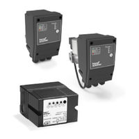
Tightness controls, Adjustable test period which can be adapted to different systems, Adjustable test instant allows quick system start, Maximum safety thanks to self-monitoring electronics
Brand:
Honeywell
| Category:
Control Unit
| Size: 4.17 MB
Table of Contents
Tightness Controls TC
1
Contents
2
Table of Contents
2
1 Application
4
Application Examples
7
TC 1V with Valvario Controls
7
TC 1C with Combination Control CG
8
TC 2 with Two Gas Solenoid Valves
9
Auxiliary Valve for Discharge
10
Auxiliary Valve for Discharge
11
TC 2 in a Multiple Burner System with Several
12
Valves Installed in Series
12
Valves Installed in Series
13
TC 4 with Two Gas Solenoid Valves
14
Auxiliary Valve for Discharge
15
TC 4 in a Multiple Burner System with Two Auxiliary Valves for Supply and Discharge
16
Valves Installed in Series
17
2 Certification
18
Tc 1, Tc 2, Tc 3
18
Tc 4
19
3 Function
20
Tc 1, Tc 2, Tc 3
20
Connection Diagrams for TC 1, TC 2
20
Connection Diagrams for TC 3
21
Test Procedure for TC 1, TC 2, TC 3
22
Test Instant TC 1, TC 2, TC 3
24
Test Instant for Mode 1: Testing before Burner Run
24
Test Instant for Mode 2: Testing after Burner Run
25
Test Instant for Mode 3: Testing before and after
26
Burner Run
26
Measurement Time T M for TC 1, TC 2, TC 3
27
Calculation Example for T M
27
Tc 4
28
Connection Diagram
28
Test Procedure TC 4
29
TC 4 Test Instant
31
Test Instant for Mode 1: Testing before Burner Run
31
Test Instant for Mode 2: Testing after Burner Run
32
For TC 4
33
Calculation Example for T P
33
Test Volume V P for TC 1, TC 2, TC 3, TC 4
34
Leakage Rate Q L
35
Animation
36
Selection
37
Tc 1, Tc 2, Tc 3
37
Selection Table
37
Type Code
37
4 Selection
37
Tc 4
37
5 Project Planning Information
38
Selecting the Auxiliary Valves
38
Start Rate
39
Installation
39
TC 1V for Solenoid Valves for Gas VAS, VCX
39
TC 1C for Combination Controls CG
39
TC 2..R: Rp ¼
40
TC 3..R: Rp ¼
40
Tc 4
40
Electrical Connection of TC 1, TC 2
41
Determining the Relief Line Size
41
6 Accessories
42
Socket
42
Valve Connection Cable
42
External Pressure Switch for TC 4
42
7 Technical Data
43
Tc 1, Tc 2, Tc 3
43
Tc 4
44
Indicators and Operating Controls
46
Dimensions
47
Converting Units
47
Safety-Specific Characteristic Values
48
8 Safety Information in Accordance with
49
EN 61508-2 for TC 1, TC 2, TC 3
49
General
49
Type of Action
49
Other Classifications
49
Electrical Data
49
Interfaces
50
Electrical Wiring
50
Connection Terminals
50
Inputs
50
Outputs
51
SIL and PL for TC 1, TC 2, TC 3
51
9 Maintenance Cycles
52
10 Glossary
53
Tightness Control
53
Valve Proving System VPS
53
Safety Interlocks
53
Diagnostic Coverage DC
53
Operating Mode
53
Hardware Fault Tolerance HFT
53
Probability of Dangerous Failure PFHD
54
Mean Time to Dangerous Failure MTTF D
54
Feedback
55
Contact
55
Advertisement
Advertisement
Related Products
Honeywell Kromschroder TC 1
Honeywell Kromschroder TC 2
Honeywell Kromschroder TC 3
Honeywell TC Series
Honeywell TC 1
Honeywell TC 1V
Honeywell TC 1C
Honeywell TC 2
Honeywell TC 3
Honeywell TR120
Honeywell Categories
Thermostat
Controller
Control Unit
Security Camera
Accessories
More Honeywell Manuals
Login
Sign In
OR
Sign in with Facebook
Sign in with Google
Upload manual
Upload from disk
Upload from URL