Sign In
Upload
Manuals
Brands
HP Manuals
Measuring Instruments
3456A
HP 3456A Manuals
Manuals and User Guides for HP 3456A. We have
2
HP 3456A manuals available for free PDF download: Operating And Service Manual
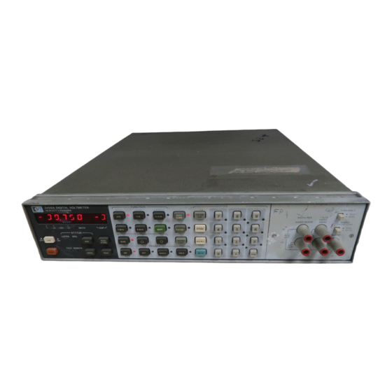
HP 3456A Operating And Service Manual (315 pages)
DIGITAL VOLTMETER
Brand:
HP
| Category:
Measuring Instruments
| Size: 25.89 MB
Table of Contents
Manual Changes
2
Table of Contents
4
Safety Summary
9
Safety Symbols
10
General Information
17
Options
17
Description
17
Specifications
17
1·11. Instrument and Manual Identification
17
1·16. Accessories Supplied
17
Specifications
18
General Information
18
Accessories Available
24
Recommended Test Equipment
24
1·20. Safety Consideration
24
General
25
Power Requirement
26
Power Cords and Receptacles
26
Grounding Requirements
26
Section 11. INSTALLATION
26
Preparation for Use
26
Rack Mounting
27
Interface Connection
27
Address Selection
27
Power Cables
27
Typical HP-IB System Interconnection
28
HP-IB Connector
28
External Trigger
29
Repackaging for Shipment
29
Address Selection
29
2·25. Voltmeter Complete Connector
29
Environmen tal Requirements
29
Operating and Storage Temperature
29
Operation
30
General Operating Characteristics
30
Reset
30
Pre-Operating Instructions
30
3·11. Turn·on and Warm·up
30
Introduction
30
Front and Rear Panel Features
31
Self Test Operation
32
Front Panel Display Area
32
Display
33
Error Messages
33
DC Voltage Measurement
33
Front Panel Voltmeter Configuration Area
33
AC Voltage Measurement
34
AC+DC Measurement
34
Resistance Measurement
34
Ohms Connection
34
Shift Operltion
35
Ratio
35
Offset Compensated Ohms Measurement (O.C. Ohms)
36
Ranging
36
Autorange
36
Instrument Trigger Modes
37
Autozero Effects on 4-Wire Ohms Measurement
37
Analog Filter
38
Storing into Registers
38
Front Panel Numbered Keyboard Area
38
Registers and Math Listing
39
Math Feature
40
Number of Power Line Cycles Integrated
40
Digits Displayed
40
Number of Readings Per Trigger
40
Optimizing Reading Rate
41
At Turn on
41
Your Signal Environment
41
Speeding the Reading Transfer
41
High Speed Scanning
42
Data Throughput
42
Waveform Characterization
42
%Error
43
Scale
43
Pass/Fail (Limit Test)
43
Null
43
Thermistor
43
Db
44
Dbm
44
Null
44
Thermistor
44
Statistics
45
Mean
45
Variance
45
Reading Storage
46
Recalling Single Readings
46
Scroll Readings
46
Voltmeter Complete
47
Guarding
47
Remote Operation
47
HP-IB Description
47
Data
48
Trigger
48
Local
48
Require Service (SRQ)
48
Status Byte
49
Status Bit
50
Abort (Unterface Clear)
50
Addressing
50
Address Codes
51
Talk-Only (no Controller)
51
HP-IB Programming
51
Algorithm
51
Data
51
Clear
51
Remote
51
Local Lockoul
51
Clear Lockout and Set Local
51
Require Service (SRQ)
51
Programming the Unit over the HP-IB
52
Program Codes (Data Received by the Unit)
52
Storing into Registers (Y, Z, Delay, Etc.) over the HP-IB
52
Program Codes Table
53
Programming the SRO Mask
54
ASCII Format
54
Overload Output Statement
54
Packed Format
54
Reading the Unit's Output Data
55
Disabling the End or Identify (EOI) Statement
55
System Output Mode
55
Home Command
55
Front/Rear Switch Position
56
Complete Program Example
56
Front Panel SAD
56
Abort (Interface Clear)
56
Programming the 3456A over
56
Instrument Program Memory Operation
57
Storing Program Codes
57
Program Execution
57
Recall of Readings from Memory
57
The Hp·ib
57
A Program Codes
57
Data Ready
58
Numeric Entry Format and Other Input Considerations
58
Operator's Check
58
DCV Test
59
Ohms Test
59
Section IV. PERFORMANCE TEST
59
ACV Test
60
Test Cards
60
Calibration Cycle
60
Test Failure
60
The 3456A)
60
Recommended Test Equipment
61
Specification Breakdown
62
Test Consideration
62
Ambiguous Region
62
General
62
DCV Test Limits
63
DCV Accuracy Test Set-Up
64
Schematic of the DCV Accuracy Test Set-Up
64
Ratio Test Connection
65
Ohms Test Limits
66
OC Common Mode Rejection Test
66
4-Wire Ohms Short
67
ACV Test
67
Alternate 250 Khz ACV Test
68
ACV Test Limits
68
Adjustments
69
Adjustment Interval
69
Adjustment Sequence
69
Introduction
69
Adjustment Location
70
DCV Adjustment
70
DCV Test Equipment Connection
71
Ohms Adjustment
72
ACV Adjustments
72
Combined Performance Test and Adjustments
73
DCV Test and Adjustments
73
Ohms Test and Adjustment
75
Ohms Test and Adjustment Limits
76
DC Common Mode Rejection Test
76
ACV Test and Adjustment Limits
77
Replaceable Parts
79
Standard Abbreviations
79
Code List of Manufacturers
80
Exchange Assemblies
80
Replaceable Parts Table
81
Chassis/Cabinet Parts View
98
A20 Board Miscellaneous Fastener Parts View
99
Top View of Chassis with PC Boards Removed
100
Bottom View of Chassis with PC Boards Installed
101
Bottom View of Chassis with PC Boards Removed
102
Side Views of Chassis
103
Front Assembly (Inside View)
104
Inguard Chassis - Front and Rear Panel
105
View of Front Terminal Assembly, Guard Switch, Front/Rear Switch
106
Inside View of Rear Terminal Assembly and AC Power Switch
107
Power Transformer and Bracket; Voltage Regulator, Zener Diode View
108
Diode, and Bracket
108
Manual Changes
109
Backdating
110
Individual ROM Signatures
114
With PC Boards Installed
115
Service
121
Safety Considerations
121
Theory of Operation
121
Outguard Section
121
Simplified Block Diagram
122
Front/Rear Switch
123
Input Protection
123
DC Volts Measurement
123
A20 Board Component Numbering Structure
124
Input Switching and "Range and Function Control Logic"
124
100 V and 1000 V Ranges
124
Fet Switching Technique
124
Gate Bias Amplifier #1
125
Charge Conditioning Circuits
125
Analog Filter
125
Autozero (AZ)
126
Input Amplifier
126
Input Switching Schematics
127
Analog-To-Digital IA/DI Converter
128
Input Amplifier Gains
128
Gain Switching
128
Traditional Dual-Slope Converter
128
Runup
129
Multi-Slope II A/D Coverter - Runup
129
S + 4 and S - 4 Slope Generation
130
Slope Generation with Input Signal Applied
130
Runup Timing
131
Readout Digit Generation During Runup
131
Rundown
131
Rundown Timing Chart
132
Rundown Slope Sequence
132
S - 3, S + 2, and S - 1 Slopes
133
Slope Generation
133
Waveform Composite (Runup and Rundown)
133
A/D Converter Circuit Description
133
Integrator Circuit
134
Slope Control Circuits
134
Analog Overload Detection Circuit
134
Digital Overload
134
12 Volt Reference
135
Circuit Description
135
Zero Comparator
135
A/D Autozero
135
Troubleshooting
135
Ohms Measurements
136
Reference Voltage Section
136
Calibration Components
136
Current Regulator
136
Ohms Current Source
137
Current Regulating Fet's Q203, Q20S, Q208, and Q209
137
Range Switching
137
High Voltage Protection Circuits
137
Simplified A/D Converter Schematic
138
Simplified Reference Schematic
139
Ohm's Current Schematic
140
Offset Compensated Ohms
141
Input Switching for Ohms Measurements
141
Autozero - 4 WIRE OHM
141
Level Shift for Low Ohms Offset Circuit
141
AC Volts Measurements
142
Input Attenuator and Amplifier
142
ACV and ACV + DCV
142
Comparator and FET Switch Operation
142
1, 10, and 100 Volt Range Switching
143
1000 Volt Range
143
Absolule Value Amplifier
143
RMS Converter
144
Squaring Amplifier
144
Averaging Amplifier
144
Square Root Amplifier
144
Ratio Measurements
145
AC Converter Stage Gains
145
AC Converter, Output Signal Path
145
AC Volts Measurements Schematics
146
Ratio Measurement, Reference High
147
Ratio Measurement, Reference Low
147
Inguard Logic (A30 Board)
148
Isolation Logic
148
Simplified Block Diagram
148
Receiver
149
Transmitter
149
Inguard Microprocessor
151
Range and Function Control
151
Analog Filter
151
Port Expander
152
Dual 1-4 Decoder A20U701
152
ALE and ALE Synchronizer
152
ALE Clock for A/D Converter
153
Frac
153
Slope Sequence During Rundown
154
FRAC Circuit Description
155
Zero-Crossing Deleclion Circuit (U3A)
155
FRAC Enable
155
Rundown Timing Chart
155
S + 0 Period
156
Glitch Suppressor
156
Lovl
156
FRAC Circuits Diagram
157
Outguard Section (A3 and A4 Boards)
159
Main Controller Circuits (A4 Board)
159
Simplified Block Diagram
159
Clock Generator
160
Address Bus Structure
160
Data Bus and Dala Transfer
161
True VMA Generalor
161
True VMA Generator, Timing Diagram
161
OBE Stretcher, Timing Diagram
161
Speed Compensating Circuits Diagram
162
Peripheral Select Decoders
163
Decoder, U19 and U17, Output Lines
163
Read Only Memory (ROM)
164
Random Access Memory (RAM)
164
Isolation Logic (A3 Board)
164
Keyboard Scan Logic
165
Keyboard Scan Circuits
165
Display Ready Circuit
166
Display and Annunciator Drive
166
Sample Rate Indicator Circuit
166
Keyboard, Display and Annunciator Circuits
166
HP-IB (A3 Board)
167
Interface Adapter
167
Bus Transceivers
168
External Trigger Circuit
168
Signature Analysis (SA) Test Modes
168
Power Supplies
169
Inguard Power Supply
169
Outguard Power Supply
169
Power Supply Ready Line
170
Troubleshooting
171
Board Removal and Installation
171
Service Group Listing
171
Inguard Grounding Structure
172
Service Group Summary
173
Component Reference Designator
173
Selecting the Self-Test
174
Self-Test Limits
174
Self-Test Troubleshooting
175
Mnemonic Definitions
176
Mnemonic Definitions and General Schematic Notes
178
Detailed Block Diagram
179
A20 Board - Input Switching - Component Locator Table
180
Input Switching Schematic
182
A20 Board - Ohm's Current Source - Component Locator Table
183
Ohms Current Source Schematic
185
A20 Board - Input Amplifier - Component Locator Table
186
Input Amplifier Schematic
188
A2D Board - A/D Converter - Component Locator Table
189
A/D Converter Schematic
191
A24 Reference Schematic
193
A25 Reference Schematic
195
Range and Function Control Logic
197
A40 Component Locator Table
198
AC Converter Schematic
200
A30 Component Locator Table
201
A30 Board Table
201
Inguard Logic Schematic
203
A4 Component Locator Table
204
Main Controller (Outguard) Schematic
206
Keyboard Scan Logic, Display and Annunciator Drive Schematic
209
Keyboard Display and Annunciators Schematic
211
Isolation Logic Schematic
214
HP-IB Logic Schematic
217
Power Supply Schematic
220
Service Group a
221
Outguard Failures and Troubleshooting
222
Turn-On Failure
222
Inoperative Display
222
Data Bus Signatures
223
Address Bus Signatures
223
ROM Select Signatures
223
Flowcharts
224
Strobe Signatures
225
RAM Select Signatures
225
Inoperative Annunciator
231
Inoperative Keyboard
231
Combined Display, Annunciator and Keyboard Failure
231
HP-IB Failure
231
Microprocessor Troubleshooting
232
Data Bus Lines Troubleshooting
232
Outguard Isolation Logic
233
Transmitter Troubleshooting
234
Receiver Troubleshooting
235
External Trigger Inoperative
236
Voltmeter Complete Inoperative
236
Hp-IB Address Selection Inoperative
236
Service Group B
237
Inguard Logic and Failure Symptoms
238
Inaccurate or Noisy Readings
239
Normal Mode Rejection
239
Range Failure 8
239
A/D Troubleshooting
240
Overload Failure
240
Constant Zero Reading
241
Inaccuracy or Noise
242
A/D Digital Circuitry Troubleshooting
244
Inguard Logic Troubleshooting
244
A/D Converter Signatures
245
A/D Slope Configuration
246
Static State of the A/D Digital Circuitry
246
Pre-Troubleshooting Information
247
Range and Inguard Logic Failure
247
Isolation Logic Troubleshooting
248
Inguard Signature Analysis Routines
249
Service Group C
252
Pre-Troubleshooting Information
252
DCV Troubleshooting
253
All Ranges Inoperative (Overload, Zero Reading, Accuracy or Noise)
253
Some Ranges Inoperative
253
Inguard Switch Closure Commands
254
Input Switching Troubleshooting
255
DCV Circuitry Isolation
255
Floating Reading
256
Inaccurale Reading
256
Overload Reading
257
Input Amplifier Troubleshooting
258
Gate Bias Amplifier
259
Saturated Output
260
Oscillating Output
260
Noisy Output
260
Ratio Failure
261
Analog Filter Failure
261
Service Group D
262
Inoperative Ohms Ranges
263
Ohms Accuracy Failures
263
Ohms Noise
263
Ohms Switch Closure Commands
264
Isolating the Ohms Circuitry
265
Ohms Protection Circuitry Troubleshooting
266
Ohms Current Source Troubleshooting
267
Zero Reading and Noise on some Ranges
268
Overload Reading on some Ranges
268
High or Low Reading on some Ranges
268
4-WR Troubleshooting
268
Range Failures and Defective Fets
269
Constant Overload, or High Positive or Negative Readings
269
4-WR Accuracy Failures
269
4-WR Noise Failures
270
DC Ohms Failure
270
Service Group E
271
Switch Closure Command Table
272
ACV and ACV+DCV Failure Isolation
272
ACV and ACV+DCV Troubleshooting
273
Input Attenuator Troubleshooting
274
Absolute Value Amp Troubleshooting
274
RMS Converter Troubleshooting
275
ACV Troubleshooting
276
Inaccuracies at All Frequencies
276
Inaccuracies at High Frequencies
276
Inaccuracies at Lower Frequencies
277
Service Group F
278
Power Supplies Troubleshooting
279
Inguard Power Supplies
279
Power Supplies Levels
280
Power Supplies Jumpers and Locations
280
Internal Adjustment Procedures
280
Reference Adjustment
280
A/D Adjustment
281
100V Adjustment
282
ACV Adjustment
283
250 Khz Adjustment
284
General HP-IB Description
285
Interface Connection and Bus Structure
285
HP-IB System Overview
286
Basic Device Communication Capabilities
286
HP-IB Messages
286
HP-IB Worksheet
287
Unpacking Program
288
Multiple Reading Transfer Programs
289
Bus Message Implementation
289
Front/Rear Switch Lock Procedure
291
Lock Installation Procedure
291
Lock Removal Procedure
291
A20U200 Signal Conditioning Fineline
292
A40U3 AC Goin Fineline
293
A20U500 A/D and Reference Fineline
294
Example Program Summary
295
Equipment Required
295
Set-Up
296
Check-Out
296
System Connection Diagram
296
Programming Examples
297
Example Program Z: Triggering Techniques
298
Example Program 3: Using a Math Function
299
Example Program 4: 3456A Internal Memory - Storing Data
299
3456A Program Codes
307
Status Byte Defintion
308
Advertisement
HP 3456A Operating And Service Manual (385 pages)
Digital voltmeter
Brand:
HP
| Category:
Measuring Instruments
| Size: 15.4 MB
Advertisement
Related Products
HP 3455A
HP 3400A
hp 3406A
HP 3437A
HP 3400B
HP 3562A
HP 3585A
HP 333A
HP 334A
HP Agilent 37717B SDH
HP Categories
Desktop
Laptop
Server
Monitor
Switch
More HP Manuals
Login
Sign In
OR
Sign in with Facebook
Sign in with Google
Upload manual
Upload from disk
Upload from URL