Sign In
Upload
Manuals
Brands
HP Manuals
Measuring Instruments
HP 8753E
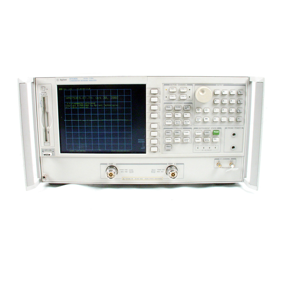
User Manuals: HP HP 8753E Network Analyzer
Manuals and User Guides for HP HP 8753E Network Analyzer. We have
4
HP HP 8753E Network Analyzer manuals available for free PDF download: User Manual, Service Manual, Programming And Command Reference Manual, Installation And Quick Start Manual
HP HP 8753E User Manual (699 pages)
network analyzer
Brand:
HP
| Category:
Measuring Instruments
| Size: 18.89 MB
Table of Contents
Safety Symbols
6
General Safety Considerations
7
Table of Contents
13
HP 8753E Description and Options
39
Front Panel Features
39
Analyzer Display
42
Rear Panel Features and Connectors
46
Analyzer Options Available
48
Option Ld5, High Stability Frequency Reference
48
Option 002, Harmonic Mode
48
Option 006,6 Ghz Operation
48
Option 010, Time Domain
48
Option 011, Receiver Configuration
48
Option 075,750 Impedance
48
Option Ldt, Delete Display
48
Option Lcm, Rack Mount Flange Kit Without Handles
48
Option Lcp, Rack Mount Flange Kit with Handles
49
Service and Support Options
49
Differences Among the HP 8753 Network Analyzers
50
Where to Look for more Information
52
Principles of Microwave Connector Care
53
Basic Measurement Sequence and Example
54
Basic Measurement Example
54
Basic Measurement Sequence
54
Step 1. Connect the Device under Test and any Required Test Equipment
54
Step 2. Choose the Measurement Parameters
54
Setting the Frequency Range
54
Setting the Measurement
55
Setting the Source Power
55
Step 3. Perform and Apply the Appropriate Error-Correction
55
Step 4. Measure the Device under Test
56
Step 5. Output the Measurement Results
56
Using the Display Functions
57
Lb View the Measurement Data and Memory Trace
58
2-4. Example of a Display Title
60
Channel Display
62
Channel Display
63
Quick Four-Parameter Display
64
Characterizing a Duplexer
64
Required Equipment
65
Procedure for Characterizing a Duplexer
65
Duplexer Measurement
67
Using Analyzer Display Markers
68
Active and Inactive Markers Example
69
Active Marker Control Example
69
Marker Information Moved into the Softkey Menu Area
70
Ib Use Delta (A) Markers
71
Marker Information on the Graticules
71
Marker 1 as the Reference Marker Example
72
Using the
73
Key
75
Lb Couple and Uncouple Display Markers
75
Example of Coupled and Uncoupled Markers
75
Example of a Log Marker in Polar Format
76
Lb Set Measurement Parameters Using Markers
77
Example of Impedance Smith Chart Markers
77
Setting the Start Frequency
78
Setting the Stop Frequency
78
Example of Setting the Center Frequency Using a Marker
79
Setting the Center Frequency
79
Example of Setting the Frequency Span Using Marker
80
Setting the Frequency Span
80
Example of Setting the Reference Value Using a Marker
81
Setting the Display Reference Value
81
Setting the Electrical Delay
82
Setting the CW Frequency
82
Example of Setting the Electrical Delay Using a Marker
82
Example of Searching for the Maximum Amplitude Using a Marker
83
Searching for the Maximum Amplitude
83
Example of Searching for the Minimum Amplitude Using a Marker
84
Searching for the Minimum Amplitude
84
Searching for a 'Lhrget Amplitude
85
Example of Searching for a Bandwidth Using Markers
86
Searching for a Bandwidth
86
Tracking the Amplitude that You Are Searching
86
RI Calculate the Statistics of the Measurement Data
87
Measuring Magnitude and Insertion Phase Response
88
Measuring the Magnitude Response
88
Device Connections for Measuring a Magnitude Response
88
Measuring Insertion Phase Response
89
Phase Samples
90
Measuring Electrical Length and Phase Distortion
91
Measuring Electrical Length
91
Linearly Changing Phase
92
Measuring Phase Distortion
93
Deviation from Linear Phase
93
Deviation from Linear Phase Example Measurement
94
Group Delay
94
Group Delay Example Measurement
95
Group Delay Example Measurement with Smoothing
95
Setting up the Measurement Parameters
97
Connections for SAW Filter Example Measurement
97
Creating Flat Limit Lines
98
Creatingaslopinglimitline
100
Example Flat Limit Lines
100
Sloping Limit Lines
101
Creating Single Point Limits
102
Editing Limit Segments
103
Deleting Limit Segments
103
Reviewing the Limit Line Segments
104
Offsetting Limit Lines
105
Measuring Gain Compression
106
Diagram of Gain Compression
106
Gain Compression Using Power Sweep
109
Measuring Gain and Reverse Isolation Simultaneously
110
Gain and Reverse Isolation
111
Measurements Using the Swept List Mode
112
Connect the Device under Test
112
Observe the Characteristics of the Filter
113
Choose the Measurement Parameters
113
Characteristics of a Filter
113
Set up the Lower Stopband Parameters
114
Calibrate and Measure
115
Filter Measurement Using Swept List Mode
116
Measurements Using the Tuned Receiver Mode
117
Compatible Sweep Types
117
Frequency Range
117
Tuned Receiver Mode In-Depth Description
117
Typical Test Setup
117
External Source Requirements
118
Test Sequencing
119
Creating a Sequence
120
Running a Sequence
121
Stopping a Sequence
121
Deleting Commands
122
Editing a Sequence
122
Inserting a Command
122
Clearing a Sequence from Memory
123
Modifying a Command
123
Changing the Sequence Title
124
Naming Files Generated by a Sequence
124
Storing a Sequence on a Disk
125
Loading a Sequence from Disk
126
Printing a Sequence
126
Purging a Sequence from Disk
126
Cascading Multiple Example Sequences
127
Loop Counter Example Sequence
128
Generating Files in a Loop Counter Example Sequence
129
Limit Test Example Sequence
130
Measuring Swept Harmonics (Option 002 Only)
132
Fundamental and 2Nd Harmonic Power Levels in Dbm
132
Nd Harmonic Power Level in Dbc
133
Measuring a Device in the Time Domain (Option 010 Only)
134
Device Connections for Time Domain Transmission Example Measurement
134
Transmission Response in Time Domain
134
Time Domain Transmission Example Measurement
135
Gating Effects in a Frequency Domain Example Measurement
138
Device Connections for Reflection Time Domain Example Measurement
139
Reflection Response in Time Domain
139
Device Response in the Frequency Domain
140
Device Response in the Time Domain
141
Non-Coaxial Measurements
142
Making Mixer Measurements
143
Where to Look for more Information
143
Measurement Considerations
144
Source and Load Mismatches
144
Reducing the Effect of Spurious Responses
144
Up Converter Port Connections
145
Frequency Offset Mode Operation
146
Differences between Internal and External R Channel Inputs
146
Power Meter Calibration
148
Conversion Loss Using the Frequency Offset Mode
149
Connections for a One-Sweep Power Meter Calibration for Mixer Measurements
151
Diagram of Measurement Frequencies
152
Measurement Setup from Display
152
Conversion Loss Example Measurement
153
High Dynamic Range Swept RF/IF Conversion Loss
154
Connections for Broad Band Power Meter Calibration
155
Connections for a High Dynamic Range Swept if Conversion Loss Measurement
157
3-13. Example of Swept if Conversion Loss Measurement
158
Fixed if Mixer Measurements
159
Tuned Receiver Mode
159
Sequence 1 Setup
159
Connections for a Response Calibration
160
Sequence 2 Setup
163
Connections for a Conversion Loss Using the Tuned Receiver Mode
164
Example Fixed if Mixer Measurement
165
Phase or Group Delay Measurements
166
Group Delay Measurement Example
168
Amplitude and Phase Tracking
169
Conversion Compression Using the Frequency Offset Mode
170
Conversion Loss and Output Power as a Function of Input Power Level Example
170
Connections for the First Portion of Conversion Compression Measurement
171
Connections for the Second Portion of Conversion Compression Measurement
172
Measurement Setup Diagram Shown on Analyzer Display
173
Example Swept Power Conversion Compression Measurement
174
Isolation Example Measurements
175
LO to RF Isolation
175
Connections for a Mixer Isolation Measurement
176
RF Feedthrough
177
Connections for a Response Calibration
178
Connections for a Mixer RF Feedthrough Measurement
178
Example Mixer RF Feedthrough Measurement
179
Printing, Plotting, and Saving Measurement Results
180
Where to Look for more Information
181
Printing or Plotting Your Measurement Results
182
Configuring a Print Function
182
Deiining a Print Function
184
Printing One Measurement Per Page
185
Printing Multiple Measurements Per Page
186
Printing Two Measurements
186
If You Are Plotting to a Pen Plotter
189
If You Are Plotting to a Disk Drive
190
Defining a Plot Function
191
Choosing Display Elements
191
Selecting Auto-Feed
191
Selecting Pen Numbers and Colors
192
Selecting Line Types
193
Line Types Available
193
Choosing Scale
194
Plotting One Measurement Per Page Using a Pen Plotter
195
Plotting Multiple Measurements Per Page Using a Pen Plotter
196
Plot Quadrants
196
Plotting a Measurement to Disk
198
Automatic File Naming Convention for LIF Format
198
Usingamipr0
200
Outputting Plot Files from a PC to a Plotter
201
Using Freelance
201
Outputting Plot Files from a PC to an HPGL Compatible Printer
202
Step 1. Store the HPGL Initialization Sequence
202
Step 2. Store the Exit HPGL Mode and Form Feed Sequence
203
Step 3. Send the HPGL Initiahzation Sequence to the Printer
203
Step 4. Send the Plot Flie to the Printer
203
Step 5. Send the Exit HPGL Mode and Form Feed Sequence to the Printer
203
Outputting Multiple Plots to a Siie Page Using a Printer
204
Plotting Multiple Measurements Per Page from Disk
205
Plot Filename Convention
205
Plot Quadrants
207
Titling the Displayed Measurement
208
Abortingaprintorplotprocess
209
Printing or Plotting the List Values or Operating Parameters
209
Solving Problems with Printing or Plotting
211
Saving and Recalling Instrument States
212
Places Where You Can Save
212
What You Can Save to the Analyzer's Internal Memory
212
Whatyoucansavetoafloppydisk
212
What You Can Save to a Computer
213
Saving an Instrument State
214
Saving Measurement Results
215
Data Processing Flow Diagram
216
ASCII Data Formats
218
S2P Data Format
218
Re-Saving an Instrument State
220
Lb Delete an Instrument State File
220
Renamingafile
221
Formatting a Disk
222
Solving Problems with Saving or Recalling Files
222
Optimizing Measurement Results
223
Increasing Measurement Accuracy
224
Connector Repeatability
224
Interconnecting Cables
224
Temperature Drift
224
Frequency Drift
225
Performance Verification
225
Reference Plane and Port Extensions
225
Where to Look for more Information
224
Measurement Error-Correction
226
Conditions Where Error-Correction Is Suggested
226
Types of Error-Correction
226
Error-Correction Stimulus State
227
Calibration Standards
228
Compensating for the Electrical Delay of Calibration Standards
228
When to Use Interpolated Error-Correction
228
Procedures for Error-Correcting Your Measurements
230
Frequency Response Error-Corrections
231
Response Error-Correction for Reflection Measurements
231
Measurement
232
Response Error-Correction for Transmission Measurements
233
Standard Connections for Response Error-Correction for Transmission
233
Receiver Calibration
234
Standard Connections for Receiver Calibration
234
Frequency Response and Isolation Error-Corrections
236
Response and Isolation Error-Correction for Reflection Measurements
236
Standard Connections for a Response and Isolation Error-Correction for Transmission Measurements
237
Response and Isolation Error-Correction for Transmission Measurements
238
Standard Connections for a Response and Isolation Error-Correction for Reflection Measurements
239
One-Port Reflection Error-Correction
240
Standard Connections for a One Port Reflection Error-Correction
241
Full Two-Port Error-Correction
243
TRL Error-Correction
246
TRM Error-Correction
247
Modifying Calibration Kit Standards
247
Definitions
251
Modifying TRL Standards
251
Modifying TRM Standards
253
Entering the Power Sensor Calibration Data
257
Editing Frequency Segments
257
Deleting Frequency Segments
258
Sample-And-Sweep Mode for Power Meter Calibration
259
Using Sample-And-Sweep Correction Mode
259
5-9. Continuous Correction Mode for Power Meter Calibration
260
Noninsertable Device
262
Calibrating for Noninsertable Devices
262
Adapter Removal
263
Perform the 2-Port Error Corrections
264
Remove the Adapter
265
Example Program
267
Matched Adapters
268
Making Accurate Measurements of Electrically Long Devices
270
Decreasing the Time Delay
271
Increasing Sweep Speed
272
Band Switch Points
273
Increasing Dynamic Range
278
Reducing Receiver Crosstalk
279
HP 8753E System Operation
283
The Receiver Block
284
Data Processing Flow Diagram
285
Ratio Calculations
286
Sampler/If Correction
286
Sweep-Lb-Sweep Averaging
286
Processing Details
286
Pre-Raw Data Arrays
287
Raw Arrays
287
Trace Math Operation
287
Gating (Option 010 Only)
287
The Electrical Delay Block
287
Conversion
287
Transform (Option 010 Only)
288
Format
288
Smoothing
288
Format Arrays
288
Offsetandscaie
288
Display Memory
288
Active Channel Keys
289
Auxiiiary Channels and Two-Port Calibration
289
Enabling Auxiiiary Channels
290
Multiple Channel Displays
290
Uncoupling Stimuius Values between Primary Channels
290
Coupled Markers
290
Entry Block Keys
290
Units Terminator
291
Knob
291
Entry Block
291
Modifying or Deleting Entries
292
Turningoffthesoftkeymenu
292
Defining Ranges with Stimulus Keys
293
Stimulus Function Block
293
Stimuius Menu
294
Stimuius Functions
293
The Power Menu
295
Understanding the Power Ranges
295
Automatic Mode
295
Manual Mode
295
Power Range Transitions in the Automatic Mode
296
Power Coupling Options
297
Channel Coupling
297
Manual Sweep Time Mode
298
Auto Sweep Time Mode
298
Minimum Sweep Time
298
Allowing Repetitive Switching of the Attenuator
301
Source Attenuator Switch Protection
301
Channel Stimulus Coupling
302
Sweep Type Menu
303
Linear Frequency Sweep (Hz)
303
Logarithmic Frequency Sweep (Hz)
304
Stepped List Frequency Sweep (Hz)
304
Stepped Edit Subsweep Menu
305
Swept List Frequency Sweep (Hz)
306
Setting Segment if Bandwidth
307
Power Sweep (Dbm)
308
Response Function Block
309
Response Functions
309
S-Parameters of a Two-Port Device
310
The S-Parameter Menu
311
Input Ports Menu
312
The Format Menu
313
Log Magnitude Format
314
Phase Format
314
Group Delay Format
315
Smith Chart Format
315
Polar Format
316
Linear Magnitude Format
317
Transmission Coefficient
317
Real Format
318
Group Delay Principles
319
Rate of Phase Change Versus Frequency
320
Electrical Delay
322
Display Menu
323
Dual Channel Displays
324
Channel Position Softkey
327
Param Displays Menu
328
Memory Math Functions
329
Setting Default Colors
330
Effect of Averaging on a Trace
332
Averaging Menu
332
Effect of Smoothing on a Trace
333
IF Bandwidth Reduction
334
Marker Menu Delta Mode Menu
336
Marker Function Menu
337
Marker Mode Menu
337
Marker Search Menu
337
Polar Marker Menu
337
Smith Marker Menu
337
Measurement Calibration
338
What Is Accuracy Enhancement
338
What Causes Measurement Errors
339
Directivity
339
Load Match
340
Source Match
340
Frequency Response (Tracking)
341
Isolation (Crosstalk)
341
Load Match
341
Characterizing Microwave Systematic Errors
342
Major Sources of Error
342
One-Port Error Model
342
Reflection Tracking Em
344
Device Measurement
347
Iwo-Port Error Model
347
Load Match ELF
349
Isolation Em
350
Source Match Esr
350
Calibration Considerations
353
Measurement Parameters
353
Device Measurements
353
Omitting Isolation Calibration
353
Saving Calibration Data
353
The Calibration Standards
354
Frequency Response of Calibration Standards
354
Electrical Offset
355
Typical Responses of Calibration Standards after Calibration
356
How Effective Is Accuracy Enhancement
357
Correcting for Measurement Errors
359
Ensuring a Valid Calibration
359
Interpolated Error-Correction
360
The Calibrate Menu
361
Response Calibration
361
Response and Isolation Calibration
361
Sll and S2 One-Port Calibration
361
Pull Two-Port Calibration
361
TRL*/LRM* Two-Port Calibration
362
Restarting a Calibration
363
Modifying Calibration Kits
364
Modify Calibration Kit Menu
365
Specify Offset Menu
368
Label Standard Menu
369
Specify Class Menu
369
Label Class Menu
372
Label Kit Menu
372
Verify Performance
372
Why Use TRL Calibration
373
How TRL*/LRM* Calibration Works
373
System
374
Isolation
375
Source Match and Load Match
376
Reflection Coefficient
378
The TRL Calibration Procedure
378
Fabricating and Defining Calibration Standards for TRL/LRM
379
Power Meter Calibration
383
Loss of Power Meter Calibration Data
384
Sample-And-Sweep Mode (One Sweep)
385
Power Loss Correction List
386
Characteristic Power Meter Calibration Sweep Speed and Accuracy
387
Notes on Accuracy
388
Alternate and Chop Sweep Modes
389
Calibrating for Noninsertable Devices
390
Instrument State Function Block
391
Using the Instrument State Functions
391
HP-IB Menu
392
System Controller Mode
393
Using the Parallel Port
394
The System Menu
395
Edit Limits Menu
396
Offset Limits Menu
397
Knowing the Instrument Modes
398
CW Frequency Range in External Source Mode
400
Frequency Offset Menu
401
Frequency Offset In-Depth Description
402
Receiver and Source Requirements
403
Harmonic Operation (Option 002 Only)
404
Accuracy and Input Power
405
Time Domain Operation (Option 010)
406
General Theory
407
Time Domain Bandpass
408
A Reflection Measurement of Two Cables
409
Interpreting the Bandpass Reflection Response Horizontal Axis
409
Transmission Measurement in Time Domain Bandpass Mode
410
Transmission Measurements Using Bandpass Mode
410
Timedomainlowpass
411
Time Domain Low Pass Measurements of an Unterminated Cable
412
Simulated Low Pass Step and Impulse Response Waveforms (Real Format)
413
Transmission Measurements in Time Domain Low Pass
414
Interpreting the Low Pass Step Transmission Response Horizontal Axis
415
Time Domain Concepts
416
Impulse Width, Sidelobes, and Windowing
417
Range
419
Resolution
420
Range Resolution
421
Response Resolution
421
Gating
422
Gate Shape
423
Selecting Gate Shape
423
Forward Transform Measurements
424
Separating the Amplitude and Phase Components of Test-Device-Induced
425
Forward Transform Range
426
Test Sequencing
427
Commands that Require a Clean Sweep
428
The Sequencing Menu
429
Sequencing Special Functions Menu
431
Loop Counter Decision Making
432
Special Commands
433
Amplifier Parameters
434
Swept Frequency Amplifier Measurement of Absolute Fundamental, 2Nd and 3Rd
434
Gain Compression
435
Diagram of Gain Compression
436
Swept Power Measurement of Amplifier's Fundamental Gain Compression and 2Nd Harmonic Output Level
436
Metering the Power Level
437
Frequency Offset
438
Mixer Parameters that You Can Measure
439
Attenuation at Mixer Ports
440
Conversion Loss Versus Output Frequency Without Attenuators at Mixer Ports
440
Example of Conversion Loss Versus Output Frequency with Correct if Signal
441
Filtering
441
Examples of up Converters and down Converters
442
Down Converter Port Connections
443
Up Converter Port Connections
444
Example Spectrum of RF, LO, and if Signals Present in a Conversion Loss
445
Conversion Compression
447
Conversion Loss and Output Power as a Function of Input Power Level
447
Connections for an Amplitude and Phase Tracking Measurement between Two
448
Connection Considerations
450
Fixtures
451
Reference Documents
452
On-Wafer Measurements
453
Dynamic Range
454
Advertisement
HP HP 8753E Service Manual (612 pages)
Network Analyzer
Brand:
HP
| Category:
Measuring Instruments
| Size: 15.15 MB
Table of Contents
Table of Contents
6
Service Equipment and Analyzer Options
28
Lhble of Service Test Equipment
28
Principles of Microwave Connector Care
32
Analyzer Options Available
34
Option Ld5, High Stability Frequency Reference
34
Option 002, Harmonic Mode
34
Optionoo6,6Ghzoperation
34
Option 010, Time Domain
34
Option 011, Receiver Configuration
34
Option 075,750 Impedance
35
Option Ldt, Delete Display
35
Option Lcm, Rack Mount Flange Kit Without Handles
35
Option Lcp, Rack Mount Flange Kit with Handies
35
Service and Support Options
36
Option W32
36
Option W34
36
System Veriikation and Performance 'Lksts
37
System Specifications
37
Performance Tests
37
How to Confirm Performance to System Specifications
39
How to Confirm Performance to Instrument Specifications
39
Certificate of Calibration
40
Sections in this Chapter
41
Performance Test Record
42
System Verification Cycle and Kit Re-Certification
43
HP 8753E System Verification
44
Initiaiization
45
Measurement Calibration
47
Device Verification
50
Test Port Output Frequency Range and Accuracy
54
External Source Mode Frequency Range
57
Incaseofdifficulty
62
In Case of Difficulty
65
In Case of Difficulty
69
Port 1 Noise Floor Level from 300 Khz to 3 Ghz (if BW = 3 Khz)
74
Port 1 Noise Floor Level from 300 Khz to 3 Ghz (if BW = 10 Hz)
75
Port 2 Noise Floor Level from 3 Ghz to 6 Ghz (if BW = 3 Khz)
76
Port 2 Noise Floor Level from 3 Ghz to 6 Ghz (if BW = 10 Hz)
77
Port 1 Noise Floor Level for 3 Ghz to 6 Ghz (if BW = 10 Hz)
77
Port 1 Noise Floor Level from 3 Ghz to 6 Ghz (if BW = 3 Khz)
77
Test Port Input Frequency Response
79
Power Meter Calibration for Test Port 1 from 300 Khz to 3 Ghz
80
Power Meter Calibration on Port 2 from 300 Khz to 3 Ghz
84
Test Port 1 Input Frequency Response from 300 Khz to 3 Ghz
85
Power Meter Calibration for Test Port 2 from 3 Ghz to 6 Ghz
85
Test Port 1 Input Frequency Response from 3 Ghz to 6 Ghz
87
Test Port 2 Input Frequency Response from 3 Ghz to 6 Ghz
89
Crosstalk to Test Port 1 from 300 Khz to 3 Ghz
91
Crosstalk to Test Port 2 from 3 Ghz to 6 Ghz
92
Calibration Coefficients
94
First Fuli 2-Port Calibration
95
Directivity (Forward) Calibration Coefficient
97
Source Match (Forward) Calibration Coefficient
97
Transmission Tracking (Forward) Calibration Coefficient
97
Reflection Tracking (Forward) Calibration Coefficient
97
System Trace Noise (Only for Analyzers Without Option 006)
101
System Trace Noise for A/R Magnitude
102
System Trace Noise for A/R Phase
102
System Trace Noise for B/R Magnitude
102
System Trace Noise for B/R Phase
103
In Case of Difficuity
103
System Trace Noise (Only for Analyzers with Option 006)
104
System Trace Noise for A/R Magnitude from 30 Khz to 3 Ghz
105
System Trace Noise for A/R Phase from 3 Ghz to 6 Ghz
105
System Trace Noise for A/R Phase from 30 Khz to 3 Ghz
106
System Trace Noise for B/R Magnitude from 30 Khz to 3 Ghz
106
System Trace Noise for B/R Magnitude from 3 Ghz to 6 Ghz
106
System Trace Noise for B/R Phase from 3 Ghz to 6 Ghz
106
System Trace Noise for B/R Phase from 30 Khz to 3 Ghz
107
12. Test Port Input Impedance
108
In Case of Difficulty
112
Initial Calcuiations
115
Power Meter Calibration
116
Adapter Removal Calibration
119
Measure Test Port 2 Magnitude Dynamic Accuracy
121
Measure Test Port 1 Magnitude Dynamic Accuracy
123
In Case of Difficulty
127
Test Port 1 Magnitude Compression
127
Test Port 2 Magnitude Compression
127
15. Test Port Receiver Phase Compression
128
Test Port 2 Phase Compression
129
Port 1 Input Worst Case 2Ndharmonic
133
Test Port Output Worst Case 3Rd Harmonic
133
Port2Inputworstcase2Ndharmonic
135
Port 2 Input Worst Case 3Rd Harmonic
136
Test Port Output Worst Case 2Nd Harmonic
138
Test Port Output Worst Case 3Rd Harmonic
139
Port 1 Input Worst Case 2Ndharmonic
140
Port2Inputworstcase2Ndharmonic
141
Port2Inputworstcase3Rdharmonic
142
Procedure
144
Performance 'Lkst Record for Analyzers with a Frequency Range of 30 Khz to 3 Ghz
162
Performance 'L&T Record
162
For Analyzers with a Frequency Range of 30 Khz to 6 Ghz
162
3 Adjustments Andcmmction Constants
178
Cavity Oscillator Frequency Correction Constants (Test 54)
205
Spur Search Procedure with a Filter
207
Spurs Search Procedure Without a Filter
208
Serial Number Correction Constants (Test 55)
211
Option Numbers Correction Constants (Test 56)
213
Initialize Eeproms (Test 58)
214
EEPROM Backup Disk Procedure
215
Correction Constants Retrieval Procedure
217
Loadingfirmware
218
Loadingfirmwareintoanexistingcpu
218
Loadingfirmwareintoanewcpu
220
Frequency Accuracy Adjustment
225
Instruments with Option ID5 Only
228
In Case of Difficulty
228
High/Low Band Transition Adjustment
229
Fractional-N Spur Avoidance and FM Sideband Adjustment
231
Source Spur Avoidance Tracking Adjustment
235
A9 Switch Positions
178
Source Default Correction Constants (Test 44)
178
Source Pretune Default Correction Constants (Test 45)
178
Analog Bus Correction Constants (Test 46)
178
Source Pretune Correction Constants (Test 48)
178
RF Output Power Correction Constants (Test 47)
178
Power Sensor Calibration Factor Entry
189
ADC Offset Correction Constants (Test 52)
194
Sampler Magnitude and Phase Correction Constants (Test 53)
195
Power Sensor Calibration Factor Entry
196
Determine the Insertion Loss of the Cable at 1 Ghz
197
Sampler Correction Constants Routine
200
Unprotected Hardware Option Numbers Correction Constants
237
How to Load Sequences from Disk
239
Sequences for Mechanical Adjustments
239
How to Set up the Fractional-N Frequency Range Adjustment
240
How to Set up the High/Low Band Transition Adjustments
240
How to Set up the Fractional-N Spur Avoidance and FM Sideband Adjustment
241
Sequence Contents
241
Sequence for the High/Low Band Transition Adjustment
241
Sequences for the Fractional-N Frequency Range Adjustment
242
Sequences for the Fractional-N Avoidance and FM Sideband Adjustment
243
4 Staxttroubleshooting here
246
Assembly Replacement Sequence
246
Having Your Analyzer Serviced
246
Step 1. Initial Observations
247
Initiate the Analyzer Self-Test
247
Step 2. Operator's Check
248
Description
248
Procedure
248
Step 3. HP-IB Systems Check
250
If Using a Plotter or Printer
251
Troubleshooting Systems with Multiple Peripherals
252
Troubleshooting Systems with Controllers
252
Step 4. Faulty Group Isolation
253
Power Supply
254
Check the Rear Panel Leds
254
Check the A8 Post Regulator Leds
254
Digital Control
255
Observe the Power up Sequence
255
Verify Intemai Tests Passed
256
Source
256
Equipment Setup for Source Power Check
258
Receiver
260
Equipment Setup
260
Accessories
262
Accessories Error Messages
262
Power Supply Troubleshooting
264
Assembly Replacement Sequence
265
Simplified Block Diagram
266
Starthere
267
Check the Green LED and Red LED on Al5
267
Check the Green Leds on A8
268
Measure the Post Regulator Voltages
268
If the Green LED of the Al5 Is Not on Steadily
270
Check the Line Voltage, Selector Switch, and Fuse
270
Check the A8 Post Regulator
271
Verify the Al5 Preregulator
272
Power Supply Cable Locations
272
Check for a Faulty Assembly
274
A15Wl Plug Detail
274
Check the Operating Temperature
276
Inspect the Motherboard
276
Remove AS, Maintain A15Wl Cable Connection
277
Check the A8 Fuses and Voltages
277
Remove the Assemblies
278
Briefly Disable the Shutdown Circuitry
279
Inspect the Motherboard
281
Error Messages
282
Check the Fuses and Isolate .A8 . 1 : 1 . 1 1 1 : 1 : 1 1 1
283
Fan Speeds
285
Check the Pan Voltages
285
Short ABTP3 to Ground
285
Intermittent Problems
286
Digital Control Troubleshooting
288
Digital Control Group Block Diagram
289
Assembly Replacement Sequence
290
CPU Troubleshooting (A9)
291
A9 CC Switch Positions
291
Checking A9 CPU Red LED Patterns
292
Switch Positions on the A9 CPU
292
Display Troubleshooting (A2, A18, A19, A27)
294
Evaluating Your Display
294
Backlight Intensity Check
295
Backlight Intensity Check Setup
296
Red, Green, or Blue Pixels Specifications
296
Dark Pixels Specifications
297
Newton's Riis
297
Newtons Rings
298
Troubleshooting a White Display
299
Troubleshooting a Black Display
299
Troubleshooting a Display with Color Problems
299
Front Panel Troubleshooting (Al, A2)
300
Check Front Panel Leds after Preset
300
Preset Sequence
300
Identify the Stuck Key
301
Inspect Cables
303
Test Using a Controller
303
Run the Internal Diagnostic Tests
304
If the Fault Is Intermittent
306
Repeat Test Function
306
Source Troubleshooting
307
Assembly Replacement Sequence
308
Before You Start Troubleshooting
308
A4 Sampler/Mixer Check
312
A3 Source and All Phase Lock Check
314
Phase Locked Output Compared to Open Loop Output in SRC
315
Waveform Integrity in SRC Tune Mode
315
YO Coil Drive Check with Oscilloscope
318
Al2 Reference Check
319
Analog Bus Method
319
Oscilloscope Method
321
PLREF Waveforms
323
Mhz Reference Signal
326
2ND lo Waveforms
327
90 Degree Phase Offset of 2Nd lo Signals in High Band
327
Lenrefline
329
A13/A14 Fractional-N Check
330
Fractional-N Check with Analog Bus
330
Al4 VCO Range Check with Oscilloscope
331
Al4 VCO Exercise
333
Al4 Divide-By-N Circuit Check
335
A7 Pulse Generator Check
338
Rechecking the A13/A14 Fractional-N
339
A7 Pulse Generator Check with Oscilloscope
340
All Phase Lock Check
341
Phase Lock Check with PLL DIAG
342
Phase Lock Diagnostic Tools
344
Phase Lock Error Messages
344
Source Group Troubleshooting Appendix
344
Troubleshooting Source Problems with the Analog Bus
344
Broadband Power Problems
345
Phase Lock Diagnostic Routines
345
Receiver Troubleshooting
346
Assembly Replacement Sequence
347
Receiver Failure Error Messages
348
Troubleshooting When au Inputs Look Bad
351
Check A10 by Substitution or Siiai Examination
353
Troubleshooting When One or more Inputs Look Good
356
Check 2Nd lo Signal at Sampler/Mixer
359
Accessories Troubleshooting
360
Assembly Replacement Sequence
361
Inspect the Accessories
362
Inspect the Test Port Connectors and Calibration Devices
362
Cable Test
364
Verify Shorts and Opens
365
Service Key Menus and Error Messages
367
Service Key Menus
367
Error Messages
367
Service Key Menus . Internal Diagnostics
368
Tests Menu
369
Test Options Menu
371
Self Diagnose Softkey
373
Test Descriptions
373
Internal Tests
373
External Tests
377
System Verification Tests
378
Adjustment Tests
379
Display Tests
381
Test Patterns
382
Service Key Menus - Service Features
384
Service Modes Menu
384
Service Modes more Menu
387
Analog Bus
388
Description of the Analog Bus
388
Themainadc
388
The Frequency Counter
389
Analog in Menu
390
Analog Bus Nodes
392
A3 Source
392
All Phase Lock
400
Al4 Fractional-N (Digital)
409
PEEK/POKE Menu
412
Firmware Revision Softkey
413
Invoking Tests Remotely
414
Analog Bus Codes
415
Error Messages
416
Error Lkrms
427
Error L&M Inspection
434
If Error Terms Seem Worse than Typical Values
435
Uncorrected Performance
435
Directivity (EDF and EDR)
437
Description
437
Affected Measurements
437
Source Match (ESF and ESR)
438
Description
438
Affected Measurements
439
Description
439
Reflection Tracking (ERF and ERR)
439
Significant System Components
439
Affected Measurements
440
Description
440
Significant System Components
440
Affected Measurements
442
Description
442
Significant System Components
442
Transmission Tracking (ETF and ETR)
442
HP HP 8753E Programming And Command Reference Manual (192 pages)
HP-IB Network Analyzer, Including Option 011
Brand:
HP
| Category:
Measuring Instruments
| Size: 2.21 MB
Table of Contents
Table of Contents
5
HP-IB Programming and Command Reference Guide
8
Where to Look for more Information
9
Preset Conditions
10
Analyzer Command Syntax
14
Code Naming Convention
14
Valid Characters
16
Units
16
Command Formats
17
General Structure
17
Syntax Types
18
Analyzer Operation
19
Held Commands
19
Operation Complete
19
Device Types
21
Listener
21
Controller
22
HP-IB Bus Structure
23
Data Bus
23
Handshake Lines
23
Control Lines
24
HP-IB Requirements
26
HP-IB Operational Capabilities
27
HP-IB Status Indicators
28
Bus Device Modes
28
System-Controller Mode
28
Lhlker/Listener Mode
30
Pass-Control Mode
30
Analyzer Bus Modes
30
Setting HP-B3 Addresses
32
Response to HP-IB Meta-Messages (IEEE-488 Universal Commands
32
Abort
32
Device Clear
32
Local
32
Local Lockout
33
Parallel Poll
33
Pass Control
33
Remote
33
Serialpoll
33
Trigger
33
Reading Analyzer Data
34
Command Query
34
Output Syntax
35
Marker Data
37
Array-Data Formats
40
Trace-Data Transfers
42
Stimulus-Related Values
43
Data-Processing Chain
44
Data Arrays
44
Fast Data Transfer Commands
46
Data Levels
47
Learn String and Calibration-Kit String
49
Error Reporting
50
Status Reporting
50
The Event-Status Register and Event-Status Register B
53
Error Output
54
Error Messages in Numerical Order
55
Calibration
61
Advertisement
HP HP 8753E Installation And Quick Start Manual (68 pages)
Network Analyzer
Brand:
HP
| Category:
Measuring Instruments
| Size: 1.54 MB
Table of Contents
Table of Contents
7
1 Installing Your Analyzer
11
Installing Your Analyzer
12
STEP 1. Verify the Shipment
13
STEP 2. Familiarize Yourself with the HP 8753E Front and Rear Panels
15
HP 8753E Front Panel
15
HP 8753E Rear Panel
16
STEP 3. Meet Electrical and Environmental Requirements
17
STEP 4. Configure the Analyzer
19
To Configure the Standard Analyzer
20
To Configure the Analyzer that Has a High Stability Frequency Reference (Option 1D5)
20
To Configure the Analyzer with Printers or Plotters
21
To Configure the Analyzer for Rack Mount Use
26
STEP 5. Verify the Analyzer Operation
30
To View the Installed Options
31
To Initiate the Analyzer Self-Test
32
To Run the Operator's Check
33
To Test the Transmission Mode
34
To Test the Reflection Mode
35
STEP 6. Back up the EEPROM Disk
36
Description
36
Equipment
36
EEPROM Backup Disk Procedure
36
2 Quick Start: Learning How to Make Measurements
39
Quick Start: Learning How to Make Measurements
40
The HP 8753E - Front Panel
41
The HP 8753E Network Analyzer Front Panel
41
Measurement Procedure
43
Step 1. Choose Measurement Parameters with Your Test Device Connected
43
Step 2. Make an Error-Correction (Measurement Calibration)
43
Step 3. Measure the Device
43
Step 4. Output Measurement Results
43
Learning to Make Transmission Measurements
44
Step 1. Choose the Measurement Parameters with Your Test Device Connected
44
Device Connections for a Transmission Measurement
44
Step 2. Make an Error-Correction (Measurement Calibration)
45
Connections for a "Thru" Calibration Standard
45
Step 3. Measure the Device
46
Example Measurement of Insertion Loss
46
Step 4. Output Measurement Results
47
Measuring Other Aspects of Insertion Loss with Marker Functions
48
Example Measurement of 3 Db Bandwidth
48
Example Measurement of Out-Of-Band Rejection
49
Example Measurement of Passband Flatness or Ripple
50
Learning to Make Reflection Measurements
51
Step 1. Choose Measurement Parameters with Your Test Device Connected
52
Step 2. Make an Error-Correction (Measurement Calibration)
53
Connections for an S 11 1-Port Error-Correction (Measurement Calibration)
53
Step 3. Measure the Device
54
Step 4. Output Measurement Results
55
Example Measurement Title
55
Measuring Other Reflection Characteristics
56
Example Standing-Wave-Ratio Measurement Trace
57
Example Admittance Measurement Trace
61
If You Encounter a Problem
62
Power-Up Problems
62
Line Fuse Removal and Replacement
62
Data Entry Problems
63
No RF Output
63
Advertisement
Related Products
HP 8753D
HP 8757C
HP 8757E
HP 8756A
HP 8754A
HP Agilent 8757D
HP 8755
HP 8719D
HP 8722D
HP 87114B
HP Categories
Desktop
Laptop
Server
Monitor
Switch
More HP Manuals
Login
Sign In
OR
Sign in with Facebook
Sign in with Google
Upload manual
Upload from disk
Upload from URL