Sign In
Upload
Manuals
Brands
Mitsubishi Electric Manuals
Controller
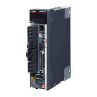
MELSERVO MR-J5-100 4 Series
Mitsubishi Electric MELSERVO MR-J5-100 4 Series Manuals
Manuals and User Guides for Mitsubishi Electric MELSERVO MR-J5-100 4 Series. We have
1
Mitsubishi Electric MELSERVO MR-J5-100 4 Series manual available for free PDF download: User Manual
Mitsubishi Electric MELSERVO MR-J5-100 4 Series User Manual (442 pages)
AC Servo System
Brand:
Mitsubishi Electric
| Category:
Controller
| Size: 43.32 MB
Table of Contents
Safety Instructions
3
About the Manual
5
Object Units
6
U.s. Customary Units
6
Table of Contents
7
Chapter 1 Function
13
Function Explanation
13
Chapter 2 Control Mode
21
Control Mode [G] [WG]
21
Control Switching
21
Cyclic Synchronous Position Mode (Csp)
22
Cyclic Synchronous Velocity Mode (Csv)
24
Cyclic Synchronous Torque Mode (Cst)
26
Profile Position Mode (Pp)
28
Profile Velocity Mode (Pv)
32
Profile Torque Mode (Tq)
36
Continuous Operation to Torque Control Mode (Ct)
39
Homing Mode (Hm) and Homing
44
Control Mode [A]
71
Control Switching
71
Position Control Mode (P)
71
Speed Control Mode (S)
75
Torque Control Mode (T)
77
Position/Speed Control Switching Mode (P/S)
80
Speed/Torque Control Switching Mode (S/T)
82
Torque/Position Control Switch Mode (T/P)
84
Chapter 3 Basic Function
85
Outline of Servo Parameter and Object Dictionary
85
Servo Parameter
85
Object Dictionary [G] [WG]
87
Rotation/Travel Direction Selection [G] [WG]
88
Setting Methods of Functions
89
Rotation/Travel Direction Selection [A]
92
Setting Methods of Functions
93
Stroke Limit Function [G] [WG]
94
Explanation of the Stroke Limit Signal Names
94
Setting Methods of Functions
95
Stop Method at Stroke Limit Detection
98
Servo Parameter List
99
Stroke Limit Function [A]
100
Setting Methods of Functions
100
Stop Method at Stroke Limit Detection
101
Servo Parameter List
101
Limit Switch Release Position Assessment Function [G] [WG]
102
Outline
102
Precautions
102
Setting Methods of Functions
102
Command Unit Select Function [G] [WG]
103
Position Command Unit Selection Function
103
Speed Command Unit Selection Function
105
Command Unit Select Function [A]
106
Torque Command Unit Selection Function
106
Electronic Gear Function [G] [WG]
107
Setting Method
107
Setting Example
108
Electronic Gear Function [A]
113
Setting Method
113
Setting Example
114
Electronic Gear Selection Function
116
In-Position Range Setting
117
Setting Method [G] [WG]
118
Setting Method [A]
118
Assigning I/O Devices
119
Setting Method [G] [WG]
120
Setting Method [A]
121
Regenerative Option Selection
122
Regenerative Option
122
Alarm Function
123
Operation Status at Alarm Occurrence [G] [WG]
123
Operation Status at Alarm Occurrence [A]
123
Operation Status at Warning Occurrence [G] [WG]
124
Operation Status at Warning Occurrence [A]
124
Returning from an Alarm [G] [WG]
125
Returning from an Alarm [A]
125
Returning from a Warning
125
Alarm History [G] [WG]
125
Alarm History [A]
127
Stop Method at Occurrence of Alarms/Warnings
127
Timing Chart at Alarm Occurrence
128
Forced Stop Deceleration Function
130
Setting Method [G] [WG]
130
Setting Method [A]
131
Timing Chart [G] [WG]
131
Timing Chart [A]
132
Electromagnetic Brake Interlock Function
133
Base Circuit Shut-Off Delay Time Function
133
Setting Method [G] [WG]
133
Setting Method [A]
134
Timing Chart
135
Vertical Axis Freefall Prevention Function
143
Setting Method [G] [WG]
143
Setting Method [A]
143
Timing Chart [G] [WG]
144
Timing Chart [A]
144
Acceleration/Deceleration Function
145
Acceleration/Deceleration Time Constant
145
S-Pattern Acceleration/Deceleration Time Constant [G] [WG]
147
S-Pattern Acceleration/Deceleration Time Constant [A]
148
Acceleration/Deceleration [G] [WG]
149
Quick Stop [G] [WG]
151
Objects for Setting
151
Timing Chart
152
Halt [G] [WG]
153
Objects for Setting
153
Timing Chart
153
Command Pulse Train Monitoring Function [A]
154
Setting a Command Frequency Error Threshold
154
Setting PEN (Command Input Permission Signal)
154
Chapter 4 Applicable Functions
155
Tough Drive Function
157
Vibration Tough Drive
157
Instantaneous Power Failure Tough Drive
157
Compliance with SEMI-F47 Standard
161
Setting Method
161
Behavior
161
Requirements of the SEMI-F47 Standard
162
Calculation Method of Tolerance against Instantaneous Power Failure
162
Scale Measurement Function [G] [WG]
163
Outline
163
Function Block Diagram
164
System Configuration
165
Scale Measurement Encoders
167
Setting Method
170
Related Objects
173
Touch Probe [G] [WG]
174
Outline
174
Setting Method
175
Machine Diagnosis
186
Friction Vibration Estimation Function
187
Friction Failure Prediction Function
193
Vibration Failure Prediction Function
202
Total Travel Distance Failure Prediction Function
208
Gear Failure Diagnosis Function
215
Belt Diagnosis Function
222
Drive Recorder
241
Specification Outline
243
How to Use the Function [G] [WG]
243
How to Use the Function [A]
246
Servo Parameter/Object Dictionary
248
Standard Acquisition Waveform List [G] [WG]
261
Standard Acquisition Waveform List [A]
263
Waveform Recording Inapplicable Alarm List
265
List of Auxiliary Recording Data
266
Software Reset
267
Software Reset in MR Configurator2
267
Software Reset Via Network Communication [G] [WG]
267
Software Position Limit [G] [WG]
268
Setting Method
268
Torque Limit [G] [WG]
271
Setting Method
271
Checking "Limiting Torque" Status
273
Torque Limit [A]
274
Setting Method
275
Checking "Limiting Torque" Status
276
Speed Limit [G] [WG]
277
Setting Method
277
Checking "Limiting Speed" Status
277
Speed Limit [A]
278
Setting Method
278
Checking "Limiting Speed" Status
280
A/B/Z-Phase Pulse Output Function
281
Setting Method [G] [WG]
282
Setting Method [A]
285
Z-Phase Pulse Output
288
Degree Unit [G] [WG]
289
Summary
289
Position-Related Data When the Unit Is Set to "Degree
290
Setting Method
291
Sequence
292
Infinite Feed Function [G] [WG]
293
Outline
293
Setting Method
293
When the Servo Motor Rotates 32768 Rev or more
293
When Using the Infinite Feed Function with a Controller
293
Servo Amplifier Life Diagnosis Function
294
Cumulative Energization Time Function
294
Relay Usage Count Display Function
295
Encoder Communication Diagnosis Function
296
Usage [G] [WG]
296
Usage [A]
297
Diagnostic Procedure
297
Disconnection/Incorrect Wiring Detection Function
298
Input Open-Phase Detection Function
298
Output Open Phase Detection Function
301
Servo Motor Incorrect Wiring Detection Function [WG]
303
Overload Protection (Electronic Thermal) Function
305
Command Offset [G] [WG]
306
Chapter 5 Monitoring
308
Explanation of Monitor Signals
308
Name and Description of the Monitor Signals
308
Signal Block Diagram
320
Checking with MR Configurator2
323
Display All" Function
323
Graph Function
323
I/O Monitor Display
324
System Configuration Display
325
Analog Monitor [G] [WG]
326
Setting Method
326
Setting Details
327
Analog Monitor [A]
331
Setting Method
331
Setting Details
332
Chapter 6 Functional Safety
336
Functions and Configuration
336
Outline
336
Outline of Safety Sub-Functions
336
Risk Assessments
337
Signal
338
Explanation of Signals
338
Power-On Sequence
340
Setting Method
341
Setting Functional Safety Parameters
341
Functional Safety Parameters that Must be Set
342
Test Operation
343
Safety Sub-Function
344
Achievable Safety Level
344
I/O Function
346
STO Function
356
SS1 Function
359
SS2/SOS Function
366
SLS Function
372
SSM Function
376
SBC Function
377
SDI Function
378
SLI Function
381
SLT Function
383
Status Monitor (SM) Function
387
Multiple Operation Commands for Safety Sub-Functions
387
Simultaneous Operation of STO and SS1 Functions
388
At Alarm Occurrence
389
Troubleshooting
391
Parameter Combinations that Trigger [AL. 537.2 Parameter Combination Error a (Safety Sub-Function)]
391
Chapter 7 Network Function
393
IP Address Setting
393
Setting an IP Address [G] [WG]
393
Setting an IP Address [A]
393
Managing Accounts
393
Setting an Account
394
Precautions
394
FTP Server Function
395
Restrictions
395
Precautions
395
Directory Structure
396
Steps of Accessing the FTP Server
396
Firmware Update
397
Chapter 8 Communication Function (Mitsubishi Electric Ac Servo Pro- Tocol) [A]
398
Structure
398
System Architecture
398
Precautions for Using the RS-422/USB Communication Function
400
Communication Specifications
401
Outline of Communication Specifications
401
Setting Servo Parameters
401
Protocol
402
Transmission Data Configuration
402
Character Codes
404
Error Codes
405
Checksum
405
Time-Out Processing
406
Retry Processing
406
Initialization
406
Communication Procedure Example
407
Command and Data No. List
408
Reading Command
408
Writing Commands
415
Detailed Explanations of Commands
417
Data Processing
417
Status Display
419
Servo Parameter
420
External I/O Signal Status (DIO Diagnosis)
423
Input Device On/Off
425
Disabling/Enabling I/O Devices (DIO)
426
Input Device On/Off (Test Operation)
426
Test Operation Mode
427
Output Signal Pin On/Off (Output Signal (DO) Forced Output)
431
Alarm History
432
Current Alarm
434
Version
435
Absolute Position Monitoring
436
Revisions
438
Warranty
439
Trademarks
440
Advertisement
Advertisement
Related Products
Mitsubishi Electric MELSERVO MR-J5-10G
Mitsubishi Electric MELSERVO MR-J5-100G
Mitsubishi Electric MELSERVO MR-J5-100G4
Mitsubishi Electric MELSERVO MR-J5-10 Series
Mitsubishi Electric MELSERVO MR-J5-100 Series
Mitsubishi Electric MELSERVO MR-J5-350G
Mitsubishi Electric MELSERVO MR-J5-60G4
Mitsubishi Electric MELSERVO MR-J5-500 Series
Mitsubishi Electric MR-J5D-G-N1
Mitsubishi Electric MR-J5-A-RJ
Mitsubishi Electric Categories
Air Conditioner
Controller
Projector
Inverter
Heat Pump
More Mitsubishi Electric Manuals
Login
Sign In
OR
Sign in with Facebook
Sign in with Google
Upload manual
Upload from disk
Upload from URL