Sign In
Upload
Manuals
Brands
Motorola Manuals
Software
MTX 838
Motorola MTX 838 Manuals
Manuals and User Guides for Motorola MTX 838. We have
3
Motorola MTX 838 manuals available for free PDF download: User Manual, Service Manual
Motorola MTX 838 User Manual (304 pages)
Radio Service Software
Brand:
Motorola
| Category:
Software
| Size: 1.14 MB
Table of Contents
Table of Contents
2
List of Tables
7
Section 1. Introduction
10
Types of RSS Programmable Features and Functions
10
Introducing the Mt 2000, Mts 2000, Mtx 838, Mtx 8000, and Mtx 9000 (Mtsx) Radio Service Software
10
Prerequisites
11
Using this Manual
12
Section 2. Getting Started and Initial Setup
14
Equipment Setup
14
Assembling the Hardware
14
Step to Connect Hardware
16
Installation Tone Identification
16
Understanding Computer Basics
17
Identifying Major Computer Parts
18
Monitor
18
System Unit
18
Keyboard
18
Understanding Computer Storage Systems
18
Random Access Memory (RAM)
19
Read Only Memory (ROM)
19
Hard-Disk Drive
19
Diskettes
19
Understanding the Disk Operating System (Dos)
20
Some DOS Commands
21
Special DOS Command Characters
22
What's on the Rss Diskettes
23
RSS Diskette(S) Contents
24
Organizing Your Hard Disk
25
Organizing Your Hard Disk and Diskettes
24
Hard Disk Directory Tree
25
Organizing Your Archive File Diskette
26
Diskette Directory Tree
26
Steps to Backup the RSS Diskette(S)
28
What to Do with Previous Versions of RSS Diskettes
29
Starting the RSS from the Hard Disk
29
Installing the RSS on Your Hard Disk
29
Starting the Rss
28
Making a Backup Copy of RSS Diskette(S)
28
RSS Hard Disk Installation Procedure
29
Installing the RSS on Multiple Computers or Networks
30
Hard Disk RSS Startup Procedure
30
Hard Disk Startup Procedures
30
The Banner Screen
31
The Main Menu
32
The Computer Keyboard
32
The Keyboard Keys and Their Functions
33
Anatomy of a Menu
35
Navigating through the Rss Menus
32
An RSS Menu
35
Anatomy of a Screen
36
An RSS Screen
36
A Complete Menu Mapping at a Glance
37
RSS Menu Mapping at a Glance
38
The Relationship between Screens
40
Changing a Field Value
41
Setting (Configuring) the Rss Computer Defaults
42
Service Software Configuration Menu Options
42
Setting Default Archive and Backup Paths
43
Creating Archive File Paths
43
Setting a Communications Port
44
Setting a Port
44
Exiting the Rss
45
Main Menu
46
How to Read the Codeplug
48
Reading the Codeplug
48
Reading Codeplug Data from the Radio
48
Reading Disk Codeplug Files
48
Setup Configuration
49
Configuring Paths and Port
50
Setting Screen Colors
52
Section 3. Basic Radio Programming Tutorial
54
Quick Steps to Bring up MAIN MENU
54
Introduction to Section
54
Programming a Basic Mt2000 Conventional Radio
55
Desired Features
55
Major Decisions Involved
55
High Level Programming Flow
55
Step-By-Step Specific Programming Instructions
55
MT2000 Button/Switch/Menu Item Defaults
57
Button Locator Diagram (Button Location Purposes Only)
58
Read Current Radio's Personality (Codeplug)
59
Program the Radio Wide Features First
59
Steps to Read a Radio's Personality (Codeplug)
59
Steps to Program Radio-Wide Features
59
Program the Phone List
60
Programming Conventional Personalties
60
Steps to Program the Phone List
60
Steps to Program Conventional Personalties
61
Program the Zone/Channel Features Next
62
Steps to Program Zone/Channel Features
62
Fill in the Scan List
63
Steps to Fill in the Scan List
63
Program the Personality into the Codeplug
64
Steps to Save Personality to Radio's Codeplug
64
Program the Personality into Archive and Backup Files
65
Steps to Save Radio Personality to Archive and Backup Files
65
Programming a Basic Mtx8000 Trunked Radio
66
Desired Features
66
Major Decisions Involved
66
High Level Programming Flow
66
Step-By-Step Specific Programming Instructions
66
Trunked Radio Personality Chart
67
MTX8000/9000 Radio Button/Switch/Menu Item Defaults
68
MTX8000/9000 Radio Button / Switch / Menu Item Defaults
68
Button Locator Diagram (Button Location Purposes Only)
69
Read Current Radio's Personality (Codeplug)
70
TCMS Merge Process
70
Program the Radio Wide Features First
70
Steps to Read a Radio's Personality (Codeplug)
70
Steps to Merge/Download TCMS
70
Steps to Assign Controls
71
Steps to Assign Button and Switch Functions
71
Program the Phone List
72
Program a Talkgroup Scan with One List
73
Steps to Program Talkgroup Scan with One Lis
73
Steps to Modify Personalities for Scan and Phone
74
Program the Zone/Channel Features Next
75
Steps to Program Zone/Channel Features
75
Steps to Fill in the Scan List
76
Program Data into Radio Codeplug
77
Steps to Save Personality to Radio's Codeplug
77
Exit the RSS
78
Desired Features
78
Major Decisions Involved
78
Steps to Exit the RSS
78
Read Desired Source Archive File
79
Clone Current Radio from Archive File
79
Cloning Remaining Radios
80
Steps to Clone Radios
80
Cloning Additional Radios
81
Exit the RSS
81
Steps to Exit the RSS
81
Additional Radio Models
82
MTS2000 Radio Button/Switch/Menu Item Defaults
83
Section 4. Service Menu Functions
84
Service Menu
84
Transmitter Alignment Menu
86
Reference Oscillator Alignment
88
Transmit Power Alignment
89
Transmit Deviation Balance (Compensation) Alignment
91
Transmit Deviation Limit Alignment
93
Transmit Deviation Limit Alignment: Reference Softpot
94
Transmit VCO Crossover Alignment
95
Secure Transmit Deviation
96
Receiver Alignment Menu
99
Front End Filter Alignment
101
Rated Audio Alignment
102
Squelch Attenuator (12.5Khz) Alignment
103
Squelch Attenuator (20Khz) Alignment
104
Receive VCO Crossover Alignment
106
Secure Receive Discriminator Level
107
Signalling Alignment Menu
108
DTMF Transmit Deviation
109
Transmit Signalling:high Speed
111
Transmit Signalling: MDC 1200
112
Section 5. Get/Save/Program Menu Functions
114
Introduction to Section
114
Get/Save/Program Menu
114
Reading Codeplug Data
116
Reading Codeplug Data from the Radio
116
Reading Codeplug Data from an Archive File
117
Radio Cloning
120
Saving Codeplug Data to an Archive File
123
Programming the Radio's Codeplug
125
Programming History
126
Section 6. Change/View Menu Functions
128
Introduction to Section
128
Change View Menu
128
Radio Wide Configuration Menu
130
Radio Wide Options
131
Radio Wide Secure Options
134
Radio Wide Emergency Options
136
More Radio Wide Options
138
Radio Wide Features Configuration Menu
140
Radio Wide Button Configuration
141
Radio Wide Switch Configuration
144
Radio Wide Menu Item Configuration
146
Phone Configuration
149
DTMF Access/Deaccess Codes
151
Radio Wide Scan Lists and Options
155
Radio Wide Scan Options
158
Radio Wide Display Options
161
Radio Wide Display more Options
164
Trunking Menu
165
Trunking Radio Wide Options
166
Smartzone Environment
168
Voice on Control Options
171
Trunking Systems
173
Channel Assignment Data
179
Control Channel
182
Trunking System Options
183
One Touch Button Options
186
Trunking Status Alias
187
Trunking Message Alias
188
Trunking Personality
189
Trunking Subfleets
195
Trunking Talkgroup
196
Trunking Emergency Data Configuration
198
Trunking Personality Options
202
Smartzone Preferred Sites
204
Trunking Call List
206
Conventional Menu
208
Conventional Radio Wide Options
210
Conventional Personality Using GE Star Signalling
212
Personality MDC Options
218
Conventional Personality Phone Options
221
More Conventional Personality Options
223
Conventional RAC Options
227
MDC Configuration Menu
229
MDC Systems
230
More Emergency Options
234
MDC System Options
235
MDC System Remote Options
238
Call List Table
240
Singletone System
244
Singletone List
246
Quik-Call II System
247
GE Star System
250
Conventional Message Alias List
253
Conventional Status Alias List
255
Zone/Talkgroup (Channel) Assignment
257
Section 7. Print Menu Functions
261
Introduction to Section
261
Print Radio Wide Features Configuration Menu
263
Trunking Menu
264
Conventional Menu
265
Section 8. File Maintenance Menu Functions
267
Introduction to Section
267
File Maintenance Menu
267
Create Directory Path
269
Delete Archive File
270
Introduction to Flashport
271
Flashing Procedure
271
Section 9. Flashport Upgrade
271
APPENDIX A Computer to Radio Communications Error Codes
275
APPENDIX B TPL Frequencies and Codes Table
275
APPENDIX C MTSX Features
277
Conventional Radio Personality Chart
283
APPENDIX D Trunking Radio Personality Chart
285
APPENDIX E Conventional Radio Personality Chart
285
Key Menu Index
285
Advertisement
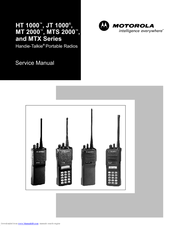
MOTOROLA MTX 838 Service Manual (170 pages)
MTX Series
Brand:
MOTOROLA
| Category:
Portable Radio
| Size: 9.74 MB
Table of Contents
Table of Contents
5
List of Tables
10
Model Numbering System
12
Model Charts Model Programming, Flashing, and Cloning
13
Model Charts General Description
13
Programming, Flashing, and Cloning
13
MODEL CHART, Conventional Systems Radios (HT 1000 Models)
14
MODEL CHART, Conventional Systems Radios (JT 1000 and MT 2000 Models)
15
MODEL CHART, Private Systems Radios (MTS 2000 Models)
16
MODEL CHART, Shared Systems Radios
17
MTX 9000 Models)
17
List of Antennas
18
List of Batteries
18
Maintenance Specifications for VHF Radios
19
Maintenance Specifications for UHF Radios
19
Maintenance Specifications for 800Mhz Radios
20
Maintenance Specifications for 900Mhz Radios
20
Glossary
21
1 Introduction
23
2 Test Equipment, Service Aids, and Tools
25
Recommended Test Equipment
25
Table 1 Recommended Test Equipment
25
Service Aids and Recommended Tools
26
Field Programming
26
Table 2 Service Aids
27
Table 3 Recommended Service Tools
28
3 Transceiver Performance Testing
29
General
29
Setup
29
Test Mode
29
Table 4 Equipment Initial Control Settings
29
Table 5 Test Environments, HT 1000/JT 1000 Radios
30
Table 6 Test Frequencies, HT 1000 / JT 1000
31
Table 7 Test Environments, MT 2000, MTS 2000, and MTX Series Radios
34
Table 8 Test Frequencies, MT 2000, MTS 2000, and MTX Series Radios
34
Table 9 Receiver Performance Checks
35
Table 10 Transmitter Performance Checks
36
4 Error-Code Displays
37
Power-Up Display Codes
37
Table 11 Power-Up Display Codes
37
Operational Display Codes
38
Table 12 Operational Display Codes
38
5 Radio Alignment Procedure
39
General
39
Reference Oscillator Alignment
41
Table 13 Reference Oscillator Alignment
41
Front-Endpre-Selector VHF/UHF Only)
42
Rated Audio
42
Table 14 Standard Test Modulation (1 Khz Tone)
42
Squelch
43
Transmitter Power
43
Transmit Deviation Balance (Compensation)
44
Table 15 Transmit Power Setting
44
Transmit Deviation Limit
45
Transmit Deviation Limit Reference
45
Table 16 Transmit Deviation Limit
45
VCO Crossover Frequency
46
Table 17 Transmit Deviation Limit Reference
46
Signalling Deviation
49
Alignment Procedure Conclusion
50
Table 18 Signalling Deviation
50
6 Disassembly and Reassembly
51
General
52
Disassembly to Board Level
52
Disassembly of Control Top
56
Disassembly of Front Cover Assembly
57
Reassembly
58
7 Maintenance
63
Introduction
63
Preventive Maintenance
63
Safe Handling of CMOS Devices
64
Repair Procedures and Techniques
64
8 Exploded Views
73
Basic Radios and Basic Radios with Option Mate Optional
74
Top-Display Radios
75
Keypad Radios
76
Uni-Board Radios
77
9 Component Location Diagrams, Parts Lists, and Schematic Diagrams
79
Introduction
79
NUD7091B, NUD7092B, NUD/PMUD7095B, and NUD7096B VHF (136-178Mhz) TRANSCEIVER BOARDS' PARTS LIST and COMPONENT LOCATION DIAGRAMS
84
Electrical Parts List, VHF Transceivers NUD7091B, NUD7092B, NUD/PMUD7095B, NUD7096B
85
BOARDS' SCHEMATIC DIAGRAM (Sheet 1 of 2)
86
BOARDS' SCHEMATIC DIAGRAM (Sheet 2 of 2)
87
NUE7265B, NUE7266B, NUE/PMUE7272B, and NUE7274B UHF (403-470Mhz) TRANSCEIVER BOARDS' PARTS LIST and COMPONENT LOCATION DIAGRAMS
88
Nue7274B
89
BOARDS' SCHEMATIC DIAGRAM (Sheet 1 of 2)
90
NUE7265B, NUE7266B, NUE/PMUE7272B, and NUE7274B UHF (403-470Mhz) TRANSCEIVER BOARDS' SCHEMATIC DIAGRAM (Sheet 2 of 2)
91
NUE7267B, NUE7268B, NUE/PMUE7273B, and NUE7275B UHF (450-520Mhz) TRANSCEIVER BOARDS' PARTS LIST and COMPONENT LOCATION DIAGRAMS
92
Nue7275B
93
NUE7267B, NUE7268B, NUE/PMUE7273B, and NUE7275B UHF (450-520Mhz) TRANSCEIVER BOARDS' SCHEMATIC DIAGRAM (Sheet 1 of 2)
94
NUE7267B, NUE7268B, NUE/PMUE7273B, and NUE7275B UHF (450-520Mhz) TRANSCEIVER BOARDS' SCHEMATIC DIAGRAM (Sheet 2 of 2)
95
NUF6410B/C, NUF6498B/C, NUF6500B/C and NUF6501C (800Mhz) TRANSCEIVER BOARDS' PARTS LIST and COMPONENT LOCATION DIAGRAMS
96
Electrical Parts List, Transceivers (800Mhz) NUF6410B/C, NUF6498B/C, NUF6500B/C and NUF6501C
97
NUF6410B/C, NUF6498B/C, NUF6500B/C and NUF6501C (800Mhz) TRANSCEIVER BOARDS' SCHEMATIC DIAGRAM (Sheet 1 of 2)
98
NUF6410B/C, NUF6498B/C, NUF6500B/C and NUF6501C (800Mhz) TRANSCEIVER BOARDS' SCHEMATIC DIAGRAM (Sheet 2 of 2)
99
NUF/PMUF6500D, NUF/PMUF6533A and NUF/PMUF6410D (800Mhz) TRANSCEIVER BOARD PARTS LIST and COMPONENT LOCATION DIAGRAMS
100
Pmuf6410D
101
NUF/PMUF6500D, NUF/PMUF6533A and NUF/PMUF6410D (800Mhz) TRANSCEIVER BOARDS' SCHEMATIC DIAGRAM (Sheet 1 of 2)
102
NUF/PMUF6500D, NUF/PMUF6533A and NUF/PMUF6410D (800Mhz) TRANSCEIVER BOARDS' SCHEMATIC DIAGRAM (Sheet 2 of 2)
103
NUF6499B/C and NUF6502B/C (900Mhz) TRANSCEIVER BOARDS' PARTS LIST and COMPONENT LOCATION DIAGRAMS
104
Electrical Parts List, Transceivers (900Mhz) NUF6499B/C and NUF6502B/C
105
(Sheet 1 of 2)
106
(Sheet 2 of 2)
107
Diagrams
108
Electrical Parts List, Transceiver (900Mhz) NUF/PMUF6499D
109
NUF/PMUF6499D (900Mhz) TRANSCEIVER BOARDS' SCHEMATIC DIAGRAM (Sheet 1 of 2)
110
NUF/PMUF6499D (900Mhz) TRANSCEIVER BOARDS' SCHEMATIC DIAGRAM (Sheet 2 of 2)
111
Ncn6145A/C, Ncn6146A, Ntn7089C, Ncn6129C, Ncn6138A, Ncn6140A/B, Ncn6141A
112
Diagrams
112
Ncn6129C, Ncn6138A, Ncn6140A/B, Ncn/Pmcn6140C, Ncn6141A, Ncn6145A/C
114
Schematic Diagram
114
Ncn6129C, Ncn6138A, Ncn6140A/B, Ncn/Pmcn6140C, Ncn6141A, Ncn6145A/C, Ncn6146A, Ntn7089C Controller Board Digital Section Schematic Diagram
115
Ncn6129C, Ncn6138A, Ncn6140A/B, Ncn/Pmcn6140C, Ncn6141A, Ncn6145A/C, Ncn6146A, Ntn7089C and Pmcn6140C Controller Board Top-Level Schematic
116
Ncn6129C, Ncn6138A, Ncn6140A/B, Ncn/Pmcn6140C, Ncn6141A, Ncn6145A/C, Ncn6146A, Ntn7089C Controller Board Power Section Schematic Diagram
117
Ncn6147A/B, Ncn6150A/B, Ntn7091D, Ntn7620E, Pmcn6147B and Pmcn6150B Controller Board' Parts List and Component Location Diagram
118
Electrical Parts List, Controllers NCN6147A/B, NCN6150A/B, NTN7091D, NTN7620E
119
Pmcn6147B, Pmcn6150B
119
Ncn6147A/B, Ncn6150A/B, Ntn7091D, Ntn7620E, Pmcn6147B and Pmcn6150B Controller Board Analog Section Schematic Diagram
120
Ncn6147A/B, Ncn6150A/B, Ntn7091D, Ntn7620E, Pmcn6147B and Pmcn6150B Controller Board Digital Section Schematic Diagram
121
Ncn6147A/B, Ncn6150A/B, Ntn7091D, Ntn7620E, Pmcn6147B and Pmcn6150B Controller Board Top-Level Schematic
122
Ncn6147A/B, Ncn6150A/B, Ntn7091D, Ntn7620E, Pmcn6147B and Pmcn6150B Controller Board Power Section Schematic Diagram
123
Ntn7512D/E, Ntn7513E, Ntn7857D/E and Ntn7858D/Econtroller Boards' Parts List and Component Location Diagrams
124
UHF and 800Mhz Radios NTN7858D/E Top/No Display 900Mhz Hear Clear Radios
125
Ntn7512D/E, Ntn7513E, Ntn7857D/E and Ntn7858D/Econtroller Board Analog Section Schematic Diagram
126
Ntn7512D/E, Ntn7513E, Ntn7857D/E and Ntn7858D/Econtroller Board Digital Section Schematic Diagram
127
Schematic
128
Ntn7512D/E, Ntn7513E, Ntn7857D/E and Ntn7858D/Econtroller Board Power Section Schematic Diagram
129
Ncn6106C, Ncn/Pmcn6153A/B, and Ncn/Pmcn6176A Controller Boards' Parts List and Component Layout Diagrams
130
Electrical Parts List, Controllers NCN6106C, NCN/PMCN6153A/B, NCN/PMCN6176A
131
Ncn6106C , Ncn/Pmcn6153A/B, Ncn/Pmcn6176A Controller Board Analog Section Schematic Diagram
132
Ncn6106C, Ncn/Pmcn6153A/B and Ncn/Pmcn6176A Controller Board Digital Section Schematic Diagram
133
Schematic
134
Ncn6106C, Ncn/Pmcn6153A/B and Ncn/Pmcn6176A Controller Board Power Section Schematic Diagram
135
Front Cover Display Flex and Controls Flex Schematic Diagrams
136
10 Replacement Parts Ordering
137
Introduction
137
Mail Orders
137
Motorola Online
137
FAX Orders
138
Parts Identification
138
Product Customer Service
138
Telephone Orders
138
Appendix A Table 1. MTS 2000 Single Key Secure Module I/O Definition
140
Appendix A Table 2. Key Variable Loader
142
Appendix A Table 3 - Secure Deviation
145
Appendix A Table 4. RSS Secure Parameters
148
Appendix B Table 1. HT 1000 Models
150
Appendix B Table 2. JT 1000 Models
152
Appendix B Table 3. MT 2000 Models
152
Appendix B Table 4. MTS 2000 Models
155
Appendix B Table 5. MTX Series Models
161
Motorola MTX 838 Service Manual (66 pages)
Handie-Talkie Portable Radios
Brand:
Motorola
| Category:
Portable Radio
| Size: 0.49 MB
Table of Contents
Table of Contents
2
Model Numbering System
5
List of Models
6
List of Antennas and Batteries
7
Maintenance Specifications for Vhf Radios
8
Maintenance Specifications for Uhf Radios
8
MAINTENANCE SPECIFICATIONS for 800Mhz RADIOS
9
MAINTENANCE SPECIFICATIONS for 900Mhz RADIOS
9
Section I. Introduction
10
Service Aids
11
Recommended and Required Test Equipment, Service Aids, and Tools Lists
11
Recommended Test Equipment
11
Service Aids and Recommended Tools
11
Field Programming
11
Recommended Service Tools
13
Initial Equipment Control Settings
14
Test Environments, HT 1000 Radios
14
Section III. Transceiver Performance Testing
14
General
14
Setup
14
Test Mode
14
Test Frequencies, HT 1000 Radios
15
Test Environments, MT 2000, MTS 2000, and MTX Series Radios
16
Receiver Performance Checks
17
Transmitter Performance Checks
18
Error Code Displays
19
Power-Up Display Codes
19
Operational Display Codes
19
Section V. Radio Alignment Procedure
20
General
20
Reference Oscillator Alignment
22
Front-End Pre-Selector (VHF/UHF Only)
22
Rated Audio
22
Squelch
22
Standard Test Modulation (1Khz Tone)
22
Transmitter Power
23
Transmit Deviation Balance (Compensation)
23
Transmit Deviation Limit
23
Transmit Power Setting
23
Transmit Deviation Limit Reference
24
VCO Crossover Frequency
24
Signalling Deviation
24
Transmit Deviation Limit
24
Section VI. Disassembly and Reassembly
26
General
26
Disassembly to Board Level
26
Disassembly of Control Top
28
Disassembly of Front Cover Assembly
29
Reassembly
30
Section VII. Maintenance
32
Introduction
32
Preventive Maintenance
32
Safe Handling of CMOS Devices
32
Repair Procedures and Techniques
32
Nud7070A, Nud7070B, Nud7085A, and Nud7085B Vhf Transceiver Boards' Component Location Diagrams and Schematic Diagram
38
Transceiver Boards' Component Location Diagrams
39
NUE7213A, NUE7213B, NUE7231A, NUE7231B, NUE7240A, and NUE7240B UHF (403-470Mhz) TRANSCEIVER BOARDS' SCHEMATIC DIAGRAM
40
NUE7213A, NUE7213B, NUE7231A, NUE7231B, NUE7240A, and NUE7240B UHF (403-470Mhz)
41
NUE7241B UHF (450-520Mhz) TRANSCEIVER BOARD COMPONENT LOCATION DIAGRAMS
41
NUE7214A, NUE7214B, NUE7232A, NUE7232B, NUE7241A, and NUE7241B UHF (450-520Mhz) TRANSCEIVER BOARDS' SCHEMATIC DIAGRAM
42
NUE7214A, NUE7214B, NUE7232A, NUE7232B, NUE7241A, and NUE7241B UHF (450-520Mhz)
43
800Mhz TRANSCEIVER BOARDS' COMPONENT LOCATION DIAGRAMS
43
NUF6394A, NUF6394B, NUF6410A, NUF6410B, NUF6423A, and NUF6423B 800Mhz TRANSCEIVER BOARDS' SCHEMATIC DIAGRAM
44
NUF6394A, NUF6394B, NUF6410A, NUF6410B, NUF6423A, and NUF6423B 800Mhz TRANSCEIVER BOARDS
44
Component Location Diagrams
45
NUF6395B, NUF6395C, NUF6424A, and NUF6424B 900Mhz TRANSCEIVER BOARDS' SCHEMATIC DIAGRAM
46
NUF6395B, NUF6395C, NUF6424A, and NUF6424B 900Mhz TRANSCEIVER BOARDS' PARTS LIST, and NTN7089A/NTN7092A CONTROLLER BOARDS' (JT 1000/HT 1000 MODELS ONLY) COMPONENT LOCATION DIAGRAMS
47
Ntn7089A/Ntn7092A Controller Boards' (Jt 1000/Ht 1000 Models Only) Schematic Diagram
48
And Ntn7091A/Ntn7093A Controller Boards' Component Location Diagrams
49
Ntn7091A/Ntn7093A Controller Boards' Schematic Diagram
50
Universal (Accessory) Connector Pin Numbers and Signal Assignments, and
51
Ntn7620B Controller Board Component Location Diagrams
51
Ntn7620B Controller Board Schematic Diagram
52
Ntn7620B Controller Board Parts List, and Ntn7512A, Ntn7513A, Ntn7857A, and Ntn7858A Controller Boards' Component Location Diagrams
53
Ntn7512A, Ntn7513A, Ntn7857A, and Ntn7858A Controller Boards' Schematic Diagram
54
Ntn7512A, Ntn7513A, Ntn7857A, and Ntn7858A Controller Boards' Parts List, Basic Radio Exploded View Diagram, Top-Display Exploded View Diagram, and Parts List
55
Keypad Radio Exploded View Diagram and Parts List
56
Integrated Circuits with Pin-Out Names
57
Appendix
60
Advertisement
Advertisement
Related Products
Motorola MTX 9000
Motorola MTX 8000
MOTOROLA MPT
Motorola FREESCALE SEMICONDUCTOR M68EZ328ADS
Motorola MOTONAV
Motorola MSP3-CNTRL-SW-1 - Mobility Services Platform Control Edition
Motorola MSP3-STGPR-SW-ED - Mobility Services Platform Provision Edition
Motorola MSP3-CNTRL-SW-100 - Mobility Services Platform Control Edition
Motorola MOSCAD
Motorola MTX850
Motorola Categories
Cell Phone
Two-Way Radio
Baby Monitor
Cordless Telephone
Radio
More Motorola Manuals
Login
Sign In
OR
Sign in with Facebook
Sign in with Google
Upload manual
Upload from disk
Upload from URL