Sign In
Upload
Manuals
Brands
Oki Manuals
Printer
C 3200
Oki C 3200 Manuals
Manuals and User Guides for Oki C 3200. We have
3
Oki C 3200 manuals available for free PDF download: Service Manual, User Manual
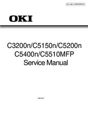
Oki C 3200 Service Manual (262 pages)
Brand:
Oki
| Category:
All in One Printer
| Size: 21.23 MB
Table of Contents
Table of Contents
4
Service Manual
1
1 Specifications
7
System Configuration
7
Printer Configuration
10
Option Configuration
15
Specifications
15
Interface Specifications
20
Parallel Interface
20
Parallel Interface Connector and Cable
20
Parallel Interface Level
20
Parallel Interface Specifications (C5400N)
20
Timing Charts
21
Parallel I/F Signals
22
Universal Serial Bus (USB) Interface Specifications
23
USB Interface
23
USB Interface Connector and Cable
23
USB Interface Signals
23
Network Interface
24
Network Interface Connector and Cable
24
Network Interface Signals
24
Network Interface Specifications(C5400/C5200/C5150/C3200N)
24
2 Operation Description
25
Electrophotographic Process Mechanism
25
Printing Processes
30
3 Printer Installation
40
Precautions and Prohibition
40
Printer Unpacking Procedure
42
Installation Space
44
Side View
44
Top View
44
Printer Installation Instructions
44
Packed Units and Attachments
45
Assembly Procedure
46
Printer Main Body
46
Power Cable Connection
51
Turning off the Printer
53
Installation of Optional Components
54
Install Memory
55
Checking of Optional-Component Recognition
63
Menumap Printing
64
Connection Procedures
67
Checking of User Paper
69
4 Parts Replacement
70
Precautions in Replacing Parts
70
Part Replacement Procedures
72
Left Side Cover
72
Right Side Cover
74
Face-Up Tray
76
Rear Cover
77
LED Assy / LED Assy-Springs
78
Controller PCB
79
Print Engine Controller PCB
83
Top Cover Assy
88
Top Cover
90
Controller Panel Assy
92
Board-Prp(C5400N//C5200N/C5150N/C3200N)/ Board-PRO(C5510MFP) / Top Cover Handle
93
Low-Voltage Power Unit / ID-FAN / Low-Voltage Power Unit FAN / Hopping Motor / Fuser Motor
94
Board-PRT
95
Guide-Eject Assy / Color Registration Assy / Board-PRM
96
FAN (Fuser) / Belt Motor / High Voltage Power Supply Board / Cover Open Switch
98
MPT-Assy
99
Feeder Unit / Board-RSF / MPT Hopping Roller / Frame Assy Separator / Cover-Front
100
Main Motors / Solenoid / Paper-End Sensor
101
Feed Roller
103
Shaft Assy-Eject (FU) / Shaft Assy-Eject (FD) / Eject Sensor
104
Fuser Unit
105
Belt Unit
106
Parts to Lubricate
107
Exploded View
121
5 Maintenance Menu
124
System Maintenance Menu(for Maintenance Staff)
124
Maintenance Utility
127
Changing the Display Language
131
Maintenance Menu Function of the User Menu
132
Maintenance Menu(for End-Users)
132
Operator Panel
133
Self-Diagnostic Mode
133
Normal Self-Diagnostic Mode (Level 1)
137
Entering Self-Diagnostic Mode (Level 1)
139
Exiting Self-Diagnostic Mode
139
Switch Scan Test
140
Motor and Clutch Test
143
Test Printing
145
Color Registration Adjustment Test
150
Print Density Adjustment Test
150
Consumable Counter Display
151
Counter Display of Numbers of Prints and Images
151
Switching between Factory and Shipping Modes
152
Self-Diagnosis Function Setting
153
LED Head Serial Number Display
154
Waste Toner Counter Display
154
Operator Panel Display
155
Printing on Controller-Equipped Printer on a Standalone Basis
160
Switch Press Functions at Printer Power-On
161
Settings after Parts Replacement
162
Instructions to Exchange the Engine Control Board
162
EEPROM Setting after ARC Board/Spy Board/Spa Board Replacement
165
Destination Setting [Check Method: Printing Demo Page (C5400) Printing Menu Map (C5200, C5150, C3200N, C5510MFP)]
166
Settings by Hand for Print Density Adjustment
168
6 Regular Maintenance
169
Parts Replaced Regularly
169
Cleaning
169
Cleaning the LED Lens Array
169
Cleaning the Led Head
170
Cleaning the Pick-Up Roller and the Pad
171
Cleaning the Printer Inside
172
7 Troubleshooting Procedures
174
Precautions before Troubleshooting
174
Precautions before Handling an Abnormal Image
174
Precautions Upon Handling an Abnormal Image
174
Preparing for Troubleshooting
174
Troubleshooting Procedure
174
LCD Message List
175
7.5.2 Preparing for Troubleshooting
187
1)LCD Display Malfunction
189
LCD Display Malfunction
189
Nothing Is Displayed in LCD
189
The First Line Is Black Display in LCD
190
Two Black Characters Turning Around
191
(The Display Changes to "COMMUNICATION ERROR" if You Leave Them as They Are)
191
An Error Message Related to the Operation Panel Is Displayed
191
2)Irregular Operation of the Device after Turning on the Power
192
Irregular Operation of the Device after Turning on the Power
192
RAM CHECK" or "INITIALIZING" Are Displayed
192
A Wrong Operation Panel Display
192
No Operation
192
Abnormal Sound
193
Abnormal Odor
194
Slow Starting Time
194
3)Paper Feed Jam(Error 391:1St Tray)
202
Paper Feed Jam(Error 391:1St Tray)
202
Paper Feed Jam Occurs Right after Turning on the Power (1St Tray)
202
Paper Feed Jam Occurs Right after Paper Feeding Starts (1St Tray)
202
4)Paper Feed Jam (Error 390:Multi-Purpose Tray)
204
Paper Feed Jam (Error 390:Multi-Purpose Tray)
204
Paper Feed Jam Occurs Right after Turning on the Power (Multi-Purpose Tray)
204
Paper Feed Jam Occurs Right after Paper Feeding Starts (Multi-Purpose Tray)
205
5)Paper Path Jam(Error 381)
206
Paper Path Jam(Error 381)
206
Paper Path Jam Occurs Right after Turning on the Power
206
Paper Path Jam Occurs Right after Feeding Paper
207
Paper Path Jam Occurs in a Path Route
209
Paper Path Jam Occurs Right after Reaching the Fuser Unit
210
6)Paper Exit Jam(Error 382)
211
Paper Exit Jam(Error 382)
211
Paper Exit Jam Occurs Right after Turning on the Power
211
Paper Exit Jam Occurs Right after Feeding Paper
212
Paper Exit Jam Occurs in a Path Route
213
7)Duplex Print Jam(Error 370,371,372,373,383)
214
Duplex Print Jam(Error 370,371,372,373,383)
214
Duplex Print Jam Occurs Right after Turning on the Power
214
Duplex Print Jam Occurs in the Duplex Entry
215
Duplex Print Jam Occurs in Reverse of the Paper
215
8)Paper Size Error (Error 400)
216
Paper Size Error (Error 400)
216
Duplex Print Jam Occurs in the Duplex Input
216
Paper Is Not Fed to a Resist Roller from Duplex Section
216
Paper Jam Occurs When the End of Paper Is Near IN1 Sensor
216
9)ID Unit Up-Down Error(Service Call 140-143)
217
ID Unit Up-Down Error(Service Call 140-143)
217
An Error Occurs in the Operation of ID Unit up
217
An Error Occurs in the Operation of ID Unit down
217
10)Fuser Unit Error(Error 170-177)
218
Fuser Unit Error(Error 170-177)
218
An Error Occurs Right after Turning on the Power
218
An Error Occurs in 1 Min. from Turning on the Power
218
11)Motor Fan Error(Error 120,127,051)
219
Motor Fan Error(Error 120,127,051)
219
Low Voltage Power Unit Fan or CU Fan Does Not Rotate Right after Turning on the Power
219
ID Cooling Fan Does Not Rotate in Printing
219
DUPLEX Fan Does Not Rotate in DUPLEX Printing
219
All Fans of the Device Do Not Rotate
219
12)Print Speed Is Slow (Low Performance)
220
Option Unit Is Not Recognized
220
Print Speed Decreases up to 2Ppm
220
Print Speed Decreases
220
Duplex Unit Is Not Recognized
220
14)LED Head Is Not Recognized(Error 131,132,133,134)
221
Print Speed Is Slow (Low Performance)
220
13)Option Unit Is Not Recognized
220
LED Head Is Not Recognized(Error 131,132,133,134)
221
2Nd Tray Unit Is Not Recognized
221
Service Call 131-134(LED HEAD Missing)
221
15)Toner Cartridge Is Not Recognized(Error 540,541,542,543)
222
Toner Cartridge Is Not Recognized(Error 540,541,542,543)
222
Errors Caused by Consumables
222
Errors Caused by Toner Sensor
224
Errors Caused by Machine Defects
225
16)Fuse Cutout Error (Error 150-155)
226
Dew Condensation Errors (Error 123)
226
Fuse Cutout Errors
226
Dew Condensation
226
Fuse Cutout Error (Error 150-155)
226
17)Dew Condensation Errors (Error 123)
226
7.5.3 Image Problem Troubleshooting
227
Image Problem Troubleshooting
227
1)Color Is Totally Pale (Fig.7.2 a )
228
Color Is Totally Pale (Fig.7.2 a )
228
Color Is Pale
228
2)Background Is Dirty (Fig.7.2 B )
229
Background Is Dirty (Fig.7.2 B )
229
Background Is Dirty (Partly)
229
Background Is Dirty (Totally)
229
3)Blank Print (Fig.7.2 C )
230
Blank Print (Fig.7.2 C )
230
Blank on the Whole Page
230
4)Vertical Lines Are Printed
231
Vertical Lines Are Printed
231
Thin Vertical Lines (with Color) (See Fig.7.2 D )
231
Thin Vertical Lines (Without Color) (See Fig.7.2 F )
231
5)Cyclic Print Trouble (Refer to Fig.7.2 E )
232
Cyclic Print Trouble (Refer to Fig.7.2 E )
232
Vertical Cyclic Print Trouble
232
6)Color Drift Is Wide
233
Color Drift Is Wide
233
IN ADJUSTING COLOR REGISTRATION" Is Shown Only a Short Time
233
Although REG ADJUST TEST of the Engine Maintenance Function Is OK, Color Drift Is Seen
233
7)Solid Black Print
234
Solid Black Print
234
Solid Black on a Full Page
234
Actions Taken after Forced Hdd/Flash Initialization
235
Network Troubleshooting
236
Displaying Details of Service Call Error Codes (C5510)
237
Fuse Checking
238
8 Connection Diagram
239
Resistance Checks
239
PCB Parts Layouts
243
Advertisement
Oki C 3200 User Manual (85 pages)
Oki Printer C3200 User's Guide
Brand:
Oki
| Category:
Printer
| Size: 2.2 MB
Table of Contents
Preface
2
Table of Contents
3
Notes, Cautions and Warnings
5
Introduction
6
Printer Overview
7
Front View
7
Rear View
8
The Status Panel
9
Switches
10
LED Displays
11
Paper Recommendations
14
Cassette Tray
15
Multi Purpose Tray
15
Face down Stacker
16
Face up Stacker
16
Loading Paper
17
Cassette Tray
17
Multi Purpose Tray
20
Printer Settings in Windows
21
Printer Driver Settings
21
Printing Preferences in Windows Applications
21
Setup Tab
22
Job Options Tab
23
Colour Tab
24
Setting from Windows Control Panel
25
General Tab
25
Advanced Tab
26
Colour Printing
28
Factors that Affect the Appearance of Prints
28
Tips for Printing in Colour
30
Printing Photographic Images
30
Printing from Microsoft Office Applications
30
Printing Specific Colours (E.g. a Company Logo)
30
Adjusting the Brightness or Intensity of a Print
30
Accessing the Colour Matching Options
31
Setting the Colour Matching Options
31
Using the Colour Swatch Feature
33
Using the Colour Correct Utility
34
The Status Monitor
35
Using the Status Monitor
35
Printer State Tab
36
Printer Setup Tab
36
Preferences Tab
39
Printer Functions (User Settings)
40
Information Menu
40
Print Menu
40
Media Menu
41
Colour Menu
44
System Configuration Menu
45
USB Menu
46
Memory Menu
47
System Adjustment Menu
47
Maintenance Menu
48
Usage Menu
49
Printing Settings
50
Changing the Display Language
50
Replacing Consumable Items
51
Consumable Order Details
52
Toner Cartridge Replacement
53
Image Drum Replacement
59
Replacing the Belt Unit
62
Fuser Replacement
65
Cleaning the LED Head
68
Installing Additional Memory>
69
Order Codes
69
Memory Upgrade
69
Clearing Paper Jams
73
Specifications
81
Index
82
Oki Contact Details
84
Oki C 3200 User Manual (2 pages)
Printers Belt Instructions
Brand:
Oki
| Category:
Printer Accessories
| Size: 2.31 MB
Advertisement
Advertisement
Related Products
Oki C3200n
Oki C330dn
Oki C331dn
Oki C3450m
Oki C3100
Oki C310dn
Oki c332
Oki C332dn
Oki C332dnw
Oki C321
Oki Categories
Printer
All in One Printer
Printer Accessories
Fax Machine
Label Maker
More Oki Manuals
Login
Sign In
OR
Sign in with Facebook
Sign in with Google
Upload manual
Upload from disk
Upload from URL