Sign In
Upload
Manuals
Brands
Panasonic Manuals
Controller
AFP7CPS31E
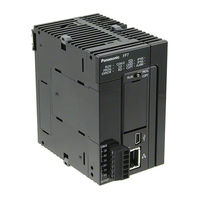
Panasonic AFP7CPS31E Manuals
Manuals and User Guides for Panasonic AFP7CPS31E. We have
6
Panasonic AFP7CPS31E manuals available for free PDF download: User Manual, Additional Functions Manual
Panasonic AFP7CPS31E User Manual (136 pages)
CPU Unit
Brand:
Panasonic
| Category:
Controller
| Size: 3.99 MB
Table of Contents
Table of Contents
6
1 Overview
11
System Configuration
12
List of Units
12
Restrictions on Combinations of Units
14
CPU Unit Type
14
Common Restrictions on each Unit
15
Restrictions on the Number of Installed Units
15
Restrictions on the Combination of Extension Cassettes
16
Restrictions on Communication Functions to be Used
16
Unit to be Used and Applicable Versions
17
Restrictions on Using Expansion Unit
18
Configuration When Using Expansion Unit
18
Restrictions on Combinations of Units
19
Installation Position of Units and Access Time
20
Restrictions on Configuration Capacity
20
Selection of Power Supply and Restrictions on Combination
22
Power Supply for Internal Circuit
22
List of Power Supply Unit's Current Consumption for Internal Circuit
24
Power Supply for External Circuit
26
Programming Tools
27
2 Names and Functions of Parts
29
CPU Unit (CPS4*/CPS3*)
30
CPU Unit (CPS21)
33
Power Supply Unit
35
Expansion Master Unit / Expansion Slave Unit
36
3 I/O Number Allocation
39
Basics of I/O Allocation
40
How to Count the I/O Numbers
40
Concept of I/O Number Allocation
40
List of Occupied I/O Points for each Unit
42
Optional Allocation Using FPWIN GR7
44
Registration of a Unit to be Used and the Starting Word Number
44
Optional Settings in the "Unit Selection" Dialog Box
46
Settings When Using Expansion Unit
47
Mount Allocation Using FPWIN GR7
48
Mount Registration of a Unit to be Used and the Starting Word Number3-10
48
Changing the Starting Word Number
49
I/O Map Registration
50
I/O Map Clearance
50
4 Installation and Wiring
51
Installation
52
Installation Environment and Space
52
Attaching Units
54
DIN Rail Attachment
56
Wiring the Power Supply
58
Common Precautions
58
Wiring for Power Supply Units
59
Wiring for the Power Supply Part of the CPU Unit
60
Wiring of Power Supply Part of Expansion Slave Unit
60
Grounding
61
Wiring of Expansion Cable
62
Expansion Cable Type
62
Connection of Function Earth Wire
62
Connecting Position and Direction of Expansion Cables
63
Safety Measures
64
Safety Circuit
64
Momentary Power Drop
64
Alarm Output
65
5 Operation
67
Before Powering on
68
Check Points
68
Procedures before Starting Operation
69
RAM/ROM Operation
70
Transmission of the Project
70
Operations Following Powering on
71
Data Hold During Power Failure
72
Online Editing
72
Backing up the Project
73
Transmission from the Execution Memory RAM to the Backup Memory ROM2
73
Transmission from the Backup Memory ROM2 to the Execution Memory RAM/ROM1
74
Operations Following Powering On/Off
74
SD Memory Card Operation
75
Preparing SD Memory Cards
75
How to Insert an SD Memory Card
76
Saving an Execution File for SD Memory Card Operation
77
Operation by an SD Memory Card
78
Transmission from an SD Memory Card to the Execution Memory
80
Precautions Concerning SD Memory Card Operation
81
Operation When Using Expansion Master Unit/Slave Unit
82
Operation When Power Supply Turns ON/OFF
82
Insertion and Removal of Expansion Cable
82
6 Troubleshooting
83
Self-Diagnosis Function
84
CPU Unit's Operation Monitor LED
84
Operation at the Time of Error
84
What to Do if an Error Occurs
85
ERROR LED Flashes on the CPU Unit
85
PROG Mode Does Not Change to RUN
86
ALARM LED Turns on on the CPU Unit
86
POWER LED Does Not Turn on on the Power Supply Unit
87
A Protect Error Message Appears
87
If Expected Output Is Not Available
88
ERR LED Turns on on the Expansion Unit
89
7 Maintenance and Inspection
91
Handling of Backup Battery
92
Functions of Backup Battery
92
Replacement of Backup Battery
93
Lifetime and Replacement Interval of Backup Battery
94
Inspection
95
8 Specifications
97
CPU Unit Specifications
98
General Specifications
98
Performance Specifications
100
CPU Unit Communication Specifications
102
Operation Memory Area
104
List of System Relays
106
List of System Data Registers
113
Error/Warning Codes Tables
116
Power Supply Unit Specifications
123
General Specifications
123
Performance Specifications
124
Alarm Output Specifications
124
Dimensions
125
Power Supply Unit
125
CPU Unit (CPS4*/CPS3*)
126
CPU Unit (CPS21)
126
Terminal Block Type Unit (1)
127
Terminal Block Type Unit (2)
127
Connector Type Unit
128
Serial Communication Unit
129
PHLS Master Unit
129
End Unit
130
Figures of Unit Combination
131
Advertisement
Panasonic AFP7CPS31E User Manual (109 pages)
CPU Unit
Brand:
Panasonic
| Category:
Controller
| Size: 2.46 MB
Table of Contents
Table of Contents
5
1 Overview
9
System Configuration
10
Units
10
Restrictions on Combinations of Units
12
Common Restrictions on each Unit
12
Restrictions on the Number of Installed Units
12
Restrictions on the Combination of Extension Cassettes
12
Restrictions on Communication Functions to be Used
13
Unit to be Used and Applicable Versions of CPU Unit and FPWIN GR71-5
13
Selection of Power Supply and Restrictions on Combination
14
Power Supply for Internal Circuit
14
Power Supply for External Circuit
17
Programming Tools
18
2 Names and Functions of Parts
19
CPU Unit
20
Power Supply Unit
22
3 I/O Number Allocation
23
Basics of I/O Allocation
24
How to Count the I/O Numbers
24
Concept of I/O Number Allocation
24
Occupied I/O Points for each Unit
25
Optional Allocation Using FPWIN GR7
26
Registration of a Unit to be Used and the Starting Word Number
26
Optional Settings in the "Unit Selection" Dialog Box
28
Mount Allocation Using FPWIN GR7
29
Mount Registration of a Unit to be Used and the Starting Word Number3-7
29
Changing the Starting Word Number
30
Automatic Allocation
31
Allocation Without Using FPWIN GR7
31
I/O Map Registration
32
I/O Map Clearance
32
4 Installation and Wiring
33
Installation
34
Installation Environment and Space
34
Attaching Units
36
DIN Rail Attachment
38
Wiring the Power Supply
40
Common Precautions
40
Wiring for Power Supply Units
41
Wiring for the Power Supply Part of the CPU Unit
42
Grounding
43
Safety Measures
44
Safety Circuit
44
Momentary Power Drop
44
Alarm Output
45
5 Operation
47
Before Powering on
48
Check Points
48
Procedures before Starting Operation
49
RAM/ROM Operation
50
Transmission of the Project
50
Operations Following Powering on
51
Data Hold During Power Failure
52
Online Editing
52
Backing up the Project
53
Transmission from the Execution Memory RAM to the Backup Memory ROM2
53
Transmission from the Backup Memory ROM2 to the Execution Memory RAM/ROM1
54
Operations Following Powering On/Off
54
SD Memory Card Operation
55
Preparing SD Memory Cards
55
How to Insert an SD Memory Card
56
Saving an Execution File for SD Memory Card Operation
57
Provisional Operation by an SD Memory Card
58
Transmission from an SD Memory Card to the Execution Memory
60
Precautions Concerning SD Memory Card Operation
61
6 Troubleshooting
63
Self-Diagnosis Function
64
CPU Unit's Operation Monitor LED
64
Operation at the Time of Error
64
What to Do if an Error Occurs
65
ERROR LED Flashes on the CPU Unit
65
PROG Mode Does Not Change to RUN
66
ALARM LED Turns on on the CPU Unit
66
POWER LED Does Not Turn on on the Power Supply Unit
67
A Protect Error Message Appears
67
If Expected Output Is Not Available
68
7 Maintenance and Inspection
71
Handling of Backup Battery
72
Functions of Backup Battery
72
Replacement of Backup Battery
73
Lifetime and Replacement Interval of Backup Battery
74
Inspection
75
8 Specifications
77
CPU Unit Specifications
78
General Specifications
78
Performance Specifications
80
CPU Unit Communication Specifications
82
Operation Memory Area
84
List of System Relays
86
List of System Data Registers
93
Error Codes Table
96
Power Supply Unit Specifications
100
General Specifications
100
Performance Specifications
101
Alarm Output Specifications
101
Dimensions
102
Power Supply Unit
102
CPU Unit
103
Terminal Block Type Unit
103
Connector Type Unit
104
Serial Communication Unit
105
PHLS Master Unit
105
End Unit
106
Figures of Unit Combination
106
Panasonic AFP7CPS31E User Manual (82 pages)
Brand:
Panasonic
| Category:
Controller
| Size: 1.67 MB
Table of Contents
Table of Contents
4
Communication Functions of CPU Unit
7
Communication Ports of CPU Unit
8
Types and Purposes of Communication Ports
8
AFP7CCET1 Port Specifications
9
Types of Communication Cassette
9
Configurator WD
9
Available Function for each COM Port
10
Applications that Can be Used in each Port
10
Restrictions
10
Overview of Communication Functions
11
MEWTOCOL Master/Slave Communication
11
General-Purpose Communication
12
Terms
13
Installation and Wiring
15
Attaching a Communication Cassette
16
Setting of Switches
16
Attachment Instructions
16
Installation Environment and Wiring for LAN Ports
17
Before Installation and Wiring
17
Installation Environment and Noise Control Measures
17
Wiring the LAN Port
18
I/O Number Allocation
19
Input/Output Signals Used for Communication
20
Occupied Area for Communication Cassette (Ethernet Type)
20
I/O Number Allocation
20
Setting Communication Conditions
23
Settings Using FPWIN GR7
24
Specified Using Configurator WD
26
Start Configurator WD and Serach Units
26
IP Address Settings
27
Communication Settings
28
Option Settings
30
Target IP Address for Unit Number Setting
32
Initialization Ot the Environment Setting of the Cassette
33
Example of User Connection (MEWTOCOL)
34
Specified Using FPWINGR7
34
Specified Using Configuration WD
34
Example of MEWTOCOL Master Communication
36
Example of User Connection (General Communication)
38
Specified Using FPWINGR7
38
Specified Using Configuration WD
38
Example of System Connection
40
Specified Using Configuration WD
40
Specified Using FPWIN GR7
41
MEWTOCOL Master/Slave Communication
43
List of MEWTOCOL / MEWTOCOL7 Supporting Commands
44
List of MEWTOCOL Commands
44
List of MEWTOCOL7 Commands
44
MEWTOCOL-COM Master Communication (RECV)
45
Read Data from an External Device
45
Precaution When Using TCP Client Mode
47
RECV Instruction (When MEWTOCOL-COM Is Used)
47
MEWTOCOL-COM Master Communication (SEND)
48
Write Data into an External Device
48
Precautions When Using TCP Client Mode
50
SEND Instruction (When MEWTOCOL-COM Is Used)
50
General-Purpose Communication
51
Operation of General-Purpose Communication
52
Read Data from an External Device
52
Write Data into an External Device
52
Sending Operation
53
Overview of Sending Operation
53
Contents of Sent Data
55
GPSEND (General-Purpose Communication Sending Instruction)
56
Precautions on Sending Data
57
Receiving Operation
58
Overview of Receiving Operation
58
Contents of Received Data
60
Precautions on Receiving Data
60
Operations of the "Reception Done Copy" Flag and Multiplex Reception
61
GPRECV (General-Purpose Communication Receiving Instruction)
62
Sending/Receiving Flag Operation
63
No Header (Start Code), Terminator (End Code) "CR
63
Start Code "STX", End Code "ETX
64
Specifications
67
Specifications
68
Communication
68
MEWTOCOL-COM Format
70
MEWTOCOL-COM Command Format
70
MEWTOCOL-COM Response Format
72
MEWTOCOL7-COM Format
74
MEWTOCOL7-COM Command Format
74
MEWTOCOL7 Response Format
76
Advertisement
Panasonic AFP7CPS31E User Manual (76 pages)
Brand:
Panasonic
| Category:
Computer Hardware
| Size: 0.95 MB
Table of Contents
Table of Contents
7
Overview of Functions
9
For Using Logging and Trace Functions
10
Precautions on Using this Function
10
Models Supporting the Logging/Trace Function
10
Selection of SD Memory Cards
10
Overview of Functions
12
Overview of Logging Function
12
Overview of Trace Function
13
Format of Saved Files
15
File Format (for Logging Function)
15
File Name (for Logging Function)
15
File Format (for Trace Function)
16
File Name (for Trace Function)
16
Data Format
17
Configuration
21
Definition of Buffer Memory
22
Setting Method
22
Logging Information Setting
23
Confirmation and Settings of File Information
23
LOG File Setting Items (for Logging)
24
Trace Information Setting
28
Confirmation and Settings of File Information
28
LOG File Setting Items (for Trace)
29
Registration of Device Information
32
Operation When Setting Cycle for Logging Trigger
34
Downloading Setting Data to CPU Unit
36
Downloading to Execution Memory RAM/ROM1
36
Copying from SD Memory Card to Execution Memory RAM/ROM1
36
Saving to SD Memory Card (in SD Memory Card Operation)
36
Precautions on Downloading Setting Data
38
Storage of Setting Data
38
Project Data Consistency
38
Autostart Setting
38
Start-Stop and Monitor
39
Start and Stop of Logging/Trace Operation
40
Start and Stop with Tool Software
40
Start and Stop with Instructions
41
Automatic Start by Setting
41
Operation Check Using Logging/Trace Monitor
42
Logging/Trace Monitor
42
System Relays Relating to Logging/Trace Operation
43
System Data Registers Relating to Logging/Trace Operation
44
Checking Logging Speed (When Selecting Logging for Application)
45
Operation Check Using System Monitor
46
Monitoring Method of System Monitor Area (SM)
46
List of System Monitor Area (SM)
46
Logging Operation
49
Flow of Logging Operation
50
Operation Flow
50
Operation When Logging Is Selected for Application
52
Operation When Logging Operation Starts
52
Operation When Logging Operation Stops
52
Operation When Power Supply Turns off
52
Operation When the Card Cover of CPU Unit Opens
52
Operation When the Number of Determination Files Reaches the Maximum Number of Generations
53
System Management Information Relating to Logging Function
55
System Management Information and Operation
55
Clearing Management Information
55
Trace Operation and Time Chart
57
Flow of Trace Operation
58
Operation When Trace Is Selected for Application
60
Operation When Trace Operation Starts
60
Operation When Logging Operation Stops
60
Operation When Power Supply Turns off
60
Operation When the Card Cover of CPU Unit Opens
60
Trace Monitor (Time Chart)
62
Display Method of Time Chart
62
Explanation of Time Chart Monitor
63
Restrictions on Time Chart Monitor
65
Troubleshooting
67
Operations When Errors Occur
68
Operation When Power Supply Turns off
68
Operation When Errors Occur (Only When Selecting Logging for Application)
68
Operations When Inserting/Removing SD Memory Card During Logging/Trace
69
Troubleshooting
70
Errors When Start/Stop Operation was Executed Using FPWIN GR7
70
Errors When Operation was Executed Using LOGST, LOGED or LOGSMPL Instruction
70
Error of Logging/Trace
71
Error When Copying Data in SD Memory Card
71
Panasonic AFP7CPS31E User Manual (86 pages)
Programmable Controller Thermocouple Multi-analog Input Unit / RTD Input Unit
Brand:
Panasonic
| Category:
Controller
| Size: 3.99 MB
Table of Contents
Table of Contents
7
Unit Functions and Restrictions
9
Unit Functions and How They Work
10
Functions of Unit
10
Unit Type and Product Number
11
Restrictions on Combinations of Units
12
Restrictions on Power Consumption
12
Applicable Versions of Unit and Software
12
Names and Functions of Parts
13
Thermocouple Multi-Analog Input Unit and RTD Input Unit
14
Wiring
15
Wiring of Terminal Block
16
Terminal Block, Suitable Wires and Tools
16
Wiring
17
Connection of Thermocouple Multi-Analog Input Unit
19
For Thermocouple Input
19
For Voltage Input
20
For Current Input
20
Connection of RTD Input Unit
22
Connection of CPU Unit Function Earth
23
Unit Settings and Data Reading
25
Confirming the I/O Number Allocations and Starting Word Number
26
Occupied I/O Area and I/O Allocation
26
Confirming Allocation of I/O Numbers
28
Configuration Settings
30
Unit Configuration
30
Unit Setting and Conversion Processing Time
32
Reading Analog Input Data
33
Data Acquisition Timing
34
Conversion Characteristics of Analog Input
37
Input Conversion Characteristics (AFP7TC8)
38
Thermocouple Input Range
38
Voltage Input Range
40
Current Input Range
42
Input Conversion Characteristics (AFP7RTD8)
43
RTD Input Range
43
Optional Settings
45
Average Processing Settings
46
Number of Averaging Times
46
Time Average
47
Moving Average
47
Offset/Gain Processing
49
Scale Conversion (AFP7TC8 Voltage/Current Range Only)
51
Comparison for Upper and Lower Limits
52
Holding Max./Min. Values
55
Disconnection Detection (AFP7TC8)
58
Disconnection Detection (AFP7RTD8)
60
Configuration by Programming
61
What to Do if an Error Occurs
63
What to Do if an Error Occurs (Analog Input)
64
Failure in Reading Input Data
64
Unstable Input Conversion Value
64
No Proper Conversion Values Obtained with Current Input
64
Specifications
65
General Specifications
66
Specifications of Thermocouple Multi-Analog Input Unit (AFP7TC8)
66
Specifications
66
Specifications of RTD Unit (AFP7RTD8)
69
I/O Number Allocation
71
List of Unit Memories
74
List of Detailed Specifications of Unit Memories
76
Dimensions
81
Panasonic AFP7CPS31E Additional Functions Manual (45 pages)
CPU Unit
Brand:
Panasonic
| Category:
Controller
| Size: 0.75 MB
Table of Contents
Table of Contents
2
1 Introduction of Ver.4.20
3
Introduction of FP7 CPU Unit Ver.4.20
4
2 Basic Instructions
7
List of Instructions
8
TM16 (16-Bit Timer)
9
CT16- (16-Bit Counter)
12
Precautions for Programming
15
3 High-Level Instructions
17
List of Instructions
18
BKEXT (16-Bit Data Sign-Extended Block Move)
19
BKMV16 (Block Move (32-Bit Data to 16-Bit Data))
21
DIVFP2 (Division (FP2 Compatible))
23
BTS (16-Bit Data Specified Bit Set)
25
BTR (16-Bit Data Specified Bit Reset)
27
4 FP2/FP2SH Program Conversion Function
29
List of Conversion Instructions to FP7
30
Conversion of Special Relays
33
Conversion of Special Data Registers
35
5 Mewtocol-Com
37
List of Commands
38
6 Multi Connection Server Function
39
Multi Connection Server Function
40
Setting Conditions and Operating Conditions
40
Precautions When Connecting Multi Connection Servers
42
How to Set Connections
43
Advertisement
Related Products
Panasonic AFP7CPS Series
Panasonic AFP7CPS4E
Panasonic AFP7CPS3E
Panasonic AFP7CPS3
Panasonic AFP7CPS41E
Panasonic AFP7CPS31
Panasonic AFP7CPS31S
Panasonic AFP7CPS31ES
Panasonic AFP7CPS41ES
Panasonic AFP7CPS21
Panasonic Categories
Camcorder
Air Conditioner
TV
Digital Camera
Cordless Telephone
More Panasonic Manuals
Login
Sign In
OR
Sign in with Facebook
Sign in with Google
Upload manual
Upload from disk
Upload from URL