Sign In
Upload
Manuals
Brands
Panasonic Manuals
Controller
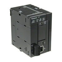
AFP7MXY32DWDH
Panasonic AFP7MXY32DWDH Manuals
Manuals and User Guides for Panasonic AFP7MXY32DWDH. We have
1
Panasonic AFP7MXY32DWDH manual available for free PDF download: User Manual
Panasonic AFP7MXY32DWDH User Manual (258 pages)
Multi Input/Output Unit
Brand:
Panasonic
| Category:
Controller
| Size: 8.25 MB
Table of Contents
1 Unit Functions and Restrictions
13
Table of Contents
13
Unit Functions and
14
Unit Functions and Operation
14
Unit Functions
14
Unit Type and Product Number
15
Restrictions on Units Combination
16
Restrictions by Power Consumption
16
Applicable Versions of FPWIN GR7 and Units
16
Restrictions on Interrupt Function
17
Restrictions on I/O Allocation
17
3 Input/Output Specifications and Wiring
25
3.1 Input/Output Specifications
26
Input/Output Specifications
26
Characteristics of Input/Output Circuits
26
I/O Terminal Layout Diagram
26
Output Specifications
29
Wiring of Input and Output
32
Common Precautions to Input and Output
32
Input Wiring
32
Output Wiring
33
Connection Using the Discrete-Wire Connector
35
Specifications of Wire-Pressed Terminal Cable
35
Wiring the Discrete-Wire Connector
36
Connection Using the Push-In Connector
39
About Push-In Connector
39
Compatible Parts and Dedicated Tools
39
Wiring to Connector
39
5 Multi I\/O Unit Setting
51
Basic Setup
52
Basic Setting Item
53
Output Terminal Setting
54
Overview
54
Allocation of Contacts to Output Terminals
55
Application to Differential Output
56
Application Setting
59
Overview
59
Setting Items by Use
59
6 Interrupt Function
63
6.1 Interrupt Function
64
Interrupt Function
64
Overview of Interrupt Function
64
Setting of Unit Body
64
Configuration Using Tool Software
64
Overview of Interrupt Program
66
Precautions for Use
67
Execution Example of Interrupt Function
68
External Interrupt Input
68
Comparison Match Interrupt
69
7 Counter Function
75
7.1 Counter Function
76
Counter Function
76
Overview of Counter Function
76
Configuration Using Tool Software
77
Linear Counter and Ring Counter
78
Selection of Count Methods
80
Control Signals
83
Reset and Mask
83
Read/Write of Elapsed Value
84
Elapsed Value When Power Turns on
84
Reading Elapsed Value
84
Changing Elapsed Value
84
Resetting/Presetting Elapsed Value
84
Elapsed Value Hold Function
86
Overview
86
Operation
87
Input Frequency Measurement Function
88
Overview
88
Reading Measurement Value
88
8 Comparison Output Function
89
8.1 Comparison Output Function
90
Comparison Output Function
90
Overview of Comparison Output Function
90
Comparison Output and Comparison Match Signal
91
Configuration Using Tool Software
91
Execution Example of Comparison Output Function
94
Comparison Output of Counter for External Input
94
9 Pulse Output/Pwm Output Function
97
9.1 Pulse Output / PWM Output Function
98
Pulse Output/Pwm Output Function
98
Overview of Pulse Output / PWM Output Function
98
Pulse Output Function Settings
98
Pulse Start Logic
99
Configuration Using Tool Software
100
Data Update Timing (Output Frequency)
102
Data Update Timing (Duty Ratio)
103
Control Signals
106
Enable and Start
106
Reset
106
Read/Write of PLS/PWM Counter Elapsed Value
108
Elapsed Value When Power Turns on
108
Reading PLS/PWM Counter Elapsed Value
108
Changing PLS/PWM Counter Elapsed Value
108
Execution Example of Pulse Output / PWM Output Function
109
Setting Example of Pulse Output
109
Setting Example of Pulse Output (Frequency Change)
110
Setting Example of Pulse Output (Comparison Match Stop)
112
Setting Example of PWM Output
114
10 Positioning Function (H Type)
117
Positioning Function
119
Overview of Positioning Function
119
Control Mode
120
Positioning Function (H Type)
119
Wiring
122
Connection Diagram with Servo Motor Amplifier
122
Connections with Servo Motor Amplifier
125
Connection with Stepping Motor Driver
125
Initial Operation Check
127
Safety Circuit Design
127
Before Turning on the Power
128
Power-On and Power-Off Sequences
129
After Turning on the Power
129
Setting of Positioning Function
131
I/O Allocation of Positioning Function
131
Configuration Using Tool Software
132
Positioning Table Settings (Configurator PMX)
136
Used Channel Setting
136
Parameter Settings
138
Creating Positioning Data Table
140
Saving Positioning Parameters
143
Export and Import
144
Check on Parameter Data
144
Writing Parameters to Unit
145
Read/Write of Elapsed Value
146
Elapsed Value (Current Value) Area
146
Reading Elapsed Value (Current Value) Area
146
Stop Control
147
Type of Stop Operations
147
Characteristics of Stop Operations
148
JOG Operation
150
Setting and Operation of JOG Operation
150
Setting and Operation of JOG Operation (Speed Changes)
152
Speed Changes in JOG Operation
155
Home Return
156
Types of Home Return
156
Operation Patterns of Home Return Operation
157
Settings and Operations of Home Return
159
Positioning Control
163
Types of Positioning Controls
163
E-Point Control (Single Speed Positioning)
164
P-Point Control (Double Speed Positioning)
166
C-Point Control
168
J-Point Control (JOG Positioning)
170
J-Point Control (JOG Positioning: Speed Changes)
173
Programming Cautions
176
Repeat Operation
177
Overview of Repeat Operation
177
Settings and Operations of Repeat Operation
178
Stop Operation During Repeat Operation
180
Linear Interpolation Control
182
Overview
182
Setting and Operation of Linear Interpolation
182
Operational Difference between Speed Parameters
185
Startup Speed
185
Operation Patterns and Start Speed Settings
185
Other Characteristics
187
Memory Backup
187
Activation of each Operation
187
Operation When CPU Mode Changes from RUN to PROG
187
12 Troubleshooting
195
Confirming Errors Using Self-Diagnostic Function
196
Checking the LED Display of Unit
196
Operation Mode When an Error Occurs
196
Troubleshooting
198
ERR LED Turns on on the Unit
198
What to Do When Positioning Error Occurs
199
ERR LED Is Flashing on the Unit
201
13 Specifications
203
13.1 Specifications
204
Specifications
204
General Specifications
204
Function Specifications (AFP7MXY32DWD/AFP7MXY32DWDH)
205
Positioning Function Specifications (AFP7MXY32DWDH)
206
Allocation of I/O Numbers
208
Input
208
Output
211
List of Unit Memories
216
Role of Unit Memories
216
List of Unit Memories (AFP7MXY32DWD/ AFP7MXY32DWDH)
217
List of Unit Memories (AFP7MXY32DWDH)
219
Unit Memory Detailed Information
226
Alarm/Error/Warning
226
Input Setting
227
Output Setting
229
Interrupt Setting Area
231
Counter Mode Setting Area
232
Counter Monitor Setting Area
233
Comparison Output Setting Area
235
Pulse Output / PWM Output Setting Area
237
Pulse Output/Pwm Output Monitor Setting Area
238
Unit Memory Detailed Information (H Type)
238
Positioning Table Area
246
Dimensions
254
Advertisement
Advertisement
Related Products
Panasonic AFP7MXY32DWD
Panasonic AFP7MC16EC
Panasonic AFP7MC32EC
Panasonic AFP7MC64EC
Panasonic AFP7CCS1
Panasonic AFP7CCM1
Panasonic AFP7CCS1M1
Panasonic AFP7Y16T
Panasonic AFP7X32D2
Panasonic AFP7CPS31
Panasonic Categories
Camcorder
Air Conditioner
TV
Digital Camera
Cordless Telephone
More Panasonic Manuals
Login
Sign In
OR
Sign in with Facebook
Sign in with Google
Upload manual
Upload from disk
Upload from URL