Sign In
Upload
Manuals
Brands
Panasonic Manuals
Controller
FP-M Hardware
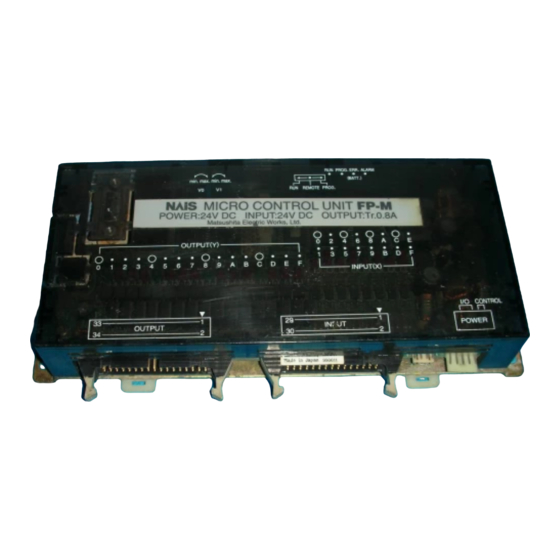
User Manuals: Panasonic FP-M Hardware Logic Controller
Manuals and User Guides for Panasonic FP-M Hardware Logic Controller. We have
1
Panasonic FP-M Hardware Logic Controller manual available for free PDF download: Manual
Panasonic FP-M Hardware Manual (268 pages)
Brand:
Panasonic
| Category:
Controller
| Size: 2.45 MB
Table of Contents
Table of Contents
3
Chapter 1 : Features
10
Features and Functions
10
Features
10
Functions
11
Advanced Control Functions
11
Network
14
Product Types
17
Control Boards
17
Expansion Boards
18
Intelligent Boards
18
Link Boards and Adapters
19
Expansion and Configurations
20
Expansion of FP-Ms
20
Restriction of Expansion
20
Expansion Boards
20
Intelligent Boards
20
Link Boards
20
Combination of Boards
21
Combination of Relay Output Type Control and Expansion Boards
21
Combination of Transistor Output Type Control and Expansion Boards
21
Programming Tools for FP-Ms
22
Programming Tools
22
NPST-GR Software
22
FP Programmer II
22
Tools for Making a Programmed ROM
23
Writing a Program to Memory (EPROM) with an FP ROM Writer
23
Writing a Program to Memory (EPROM) with NPST-GR Software and a Commercially Available ROM Programmer
23
Writing a Program to the Memory (EPROM) Via the Master Memory (EEPROM) with a Commercially Available ROM Programmer
24
Specifications and Parts Terminology
25
Chapter 2 : Specifications and Parts Terminology
26
Specifications of Control Board and Expansion Board
26
General
26
Performance
26
Input
28
Output
28
Relay Output Type
28
Transistor Output Type (PNP and NPN Open Collector)
29
Parts Terminology
30
Control Boards
30
C20R and C20RC Types
30
C20T and C20TC Types
32
C32T and C32TC Types
34
Expansion Boards
36
E20R Type
36
M1T-E Type
37
M1T-EI Type
38
M1T-EO Type
39
Board and Case Structure
40
Board Type
40
Case Type
40
Dimensions
41
Board Type
41
Control Boards
41
Expansion Boards
41
Building Dimensions
42
Mounting Hole Dimensions
42
Case Type
43
Case Dimensions for Control, Expansion, Intelligent and Link Boards
43
Building Dimensions
43
Mounting Hole Dimensions
43
Chapter 3: I/O Allocation
45
I/O Allocation of Control Boards
46
I/O Allocation of Expansion Boards
47
I/O Allocation Examples
48
Chapter 4 : Installation and Wiring
50
Stacking the Boards
50
Board Type
50
Case Type
51
Installation
52
Panel Mount
52
Board Type Mounting Method (Without Mounting Plate)
52
Case Type Mounting Method (Using Mounting Plate)
52
DIN Rail Mount
52
Cautions
53
Wiring
54
Power Supply Wiring
54
Wiring for Power Supply
54
Power Supply Lines
54
Grounding
55
Momentary Power Drop
55
Safety
55
Input and Output Wiring (Control and Expansion Boards)
56
Wiring for I/O Power Supply (C20R Control Board and E20R Expansion Board)
56
Wiring Description for I/O Power Supply (C20R Control Board and E20R Expansion Board)
57
Wiring for I/O Power Supply (C20T, C32T, M1T-E, M1T-EI, and M1T-EO Series)
58
Wiring Description for I/O Power Supply (C20T, C32T, M1T-E, M1T-EI, and M1T-EO Series)
59
Wiring for I/O Connectors (MIL Connector)
63
Wiring for I/O Terminals
69
Wiring for Programming Tool Port
70
Wiring for RS232C Port
70
Wiring Diagram and Pin Layouts
71
Control Boards
71
Expansion Boards
76
Chapter 5 : before Programming
82
Operating Principles of the Programmable Controller
82
Basic Configuration
82
Basic Operation
84
Before Turning the Power on
86
Things to Check before Turning the Power on
86
Operation Procedure
87
How to Program the Programmable Controller
88
Making a Ladder Diagram
88
Relays and Timer/Counter Contacts in the FP-M
89
I/O Allocation in the FP-M
91
Control Boards
91
Expansion Boards
91
Programming with NPST-GR Software
92
System Configuration
92
Features of NPST-GR Software Ver. 3
93
NPST-GR Configuration
94
Overview of the Programming Screen
94
Overview of the Menu Window
96
NPST-GR Installation and Configuration
97
Preparing for Installation
97
NPST-GR Installation
98
How to Use NPST-GR Effectively
100
NPST-GR Startup
100
Configuring NPST-GR
101
Exiting NPST-GR
103
Basic Key Operation for Programs
104
Downloading a Program to the Programmable Controller
105
Saving a Program to Disk
106
Printing
107
Programming with FP Programmer II
108
System Configuration
108
Downloading a Program to the Programmable Controller
109
RAM and ROM Operations
111
Operation Without Backup Battery Enabled
112
Notes on Operation with Memory (ROM Operation)
113
How to Program ROM
114
Memory (ROM) Type
114
Install the Memory (ROM)
115
How to Program ROM
115
Writing a Program to the Memory (EPROM) Via Master Memory (EEPROM) with a Commercially Available ROM Programmer
115
Writing a Program to the Memory (EPROM) with NPST-GR Software and a Commercially Available ROM Programmer
117
Chapter 6 : Troubleshooting and Maintenance
120
Self-Diagnostic Function
120
Operation Monitor Leds When an Error Occurs
120
Operation Status When an Error Occurs
121
Duplicated Output Error (Total-Check Error)
121
Battery Error (Self-Diagnostic Error)
121
Operation Error (Self-Diagnostic Error)
121
Troubleshooting
122
Points to be Checked When an Error Occurs
122
Error Codes
131
Table of Total-Check Error Codes
131
Table of Self-Diagnostic Error Codes
132
Maintenance
133
Replacement of Backup Battery
133
Battery Life
133
Using Backup Battery Type
133
How to Replace Backup Battery
133
Check Items
134
Chapter 7 : Intelligent and Link Boards
136
Analog I/O Board
136
Specifications
136
General
136
Performance
136
Restriction of Expansion
137
Dimensions
137
Parts Terminology
138
Wiring
140
A/D Converter Board
141
Specifications
141
General
141
Performance
141
Restriction of Expansion
142
Dimensions
142
Parts Terminology
143
Wiring
145
D/A Converter Board
146
Specifications
146
General
146
Performance
146
Restriction of Expansion
147
Dimensions
147
Parts Terminology
148
Wiring
150
Programming for Analog I/O, A/D Converter, and D/A Converter Boards
151
Digital Values of Analog Input
151
Digital Values of Analog Output
152
Specification of Analog I/O Data
154
Applications
155
High-Speed Counter Board
156
Specifications
156
General
156
Performance
156
Differences in Specifications between High-Speed Counter Function with FP-M Control Board and High-Speed Counter Board
157
Restriction of Expansion
158
Dimensions
158
Parts Terminology
159
I/O Allocation
161
Wiring
164
Programming for High-Speed Counter Board
165
High-Speed Counter Board Related Instructions F0 (MV), F1 (DMV)
165
Notes on Programming the High-Speed Counter
166
Applications
167
FP-M Transmitter Master Board (MEWNET-TR)
169
Specifications
170
General
170
Performance
170
Restriction of Expansion
170
Dimensions
170
Parts Terminology
171
FP-M I/O Link Board (MEWNET-F)
173
Specifications
174
General
174
Performance
174
Restriction of Expansion
174
Dimensions
174
Parts Terminology
175
Chapter 8 : Appendix
178
Performance Specifications
178
Control and Expansion Board Specifications
178
Intelligent Boards Specifications
181
Analog I/O Board Specifications
181
A/D Converter and D/A Converter Board Specifications
182
High-Speed Counter Board Specifications
183
FP-M Transmitter Master Board (MEWNET-TR) Specifications
184
FP-M I/O Link Board (MEWNET-F) Specifications
184
Dimensions
185
Board Type
185
Control Boards
185
Expansion Boards
185
Intelligent and Link Boards
186
Building Dimensions
187
Mounting Hole Dimensions
187
Case Type
188
Case Dimensions for Control, Expansion, Intelligent and Link Boards
188
Building Dimensions
188
Mounting Hole Dimensions
188
I/O Allocation Table
189
I/O Allocation of Control Boards
189
I/O Allocation of Expansion Boards
189
Allocation of Analog I/O, A/D Converter, and D/A Converter Boards
190
Allocation of High-Speed Counter Board
191
I/O Allocation of FP-M Transmitter Master Board
192
I/O Allocation of FP-M I/O Link Board
192
Table of Memory Areas
193
System Registers
195
What Are System Registers
195
Table of the System Registers
197
Special Internal Relays
206
Special Data Registers
209
Table of the Error Codes
218
Table of Total-Check Error Codes
218
Table of Self-Diagnostic Error Codes
219
Table of Instructions
220
Basic Instructions
220
High-Level Instructions
223
Table of Binary/Bcd Expressions
227
Versions of Programming Tools
228
Differences between NPST-GR Ver. 2.4 and 3.1
228
Differences between the FP Programmer and FP Programmer II
230
Modem Communication
232
Using the Programming Tool Port (FP-M Control Board All Types)
232
Using the Programming Tools Port
232
Using the RS232C Port [FP-M C Type Control Boards (C20RC/C20TC/C32TC)]
235
Using the RS232C Port
235
Terminology
240
Product Types
247
Case Type
247
Product Type
247
Board Type
249
Programming Tools
252
Wiring Parts for I/O Terminal
258
Wiring Parts for I/O Connectors (MIL Connectors)
258
Accessories
260
Maintenance Parts
261
Index
262
Record of Changes
266
Advertisement
Advertisement
Related Products
Panasonic FP0-TC8
Panasonic FPG-C32T2H
Panasonic FPG-C24R2H
Panasonic FPG-XY64D2P
Panasonic FP0-E16XA
Panasonic FP0-E8YRSA
Panasonic FP0-A04V
Panasonic FPG-C28P2TM
Panasonic FPG-C32T2H-A
Panasonic FPG-COM4-A
Panasonic Categories
Camcorder
Air Conditioner
TV
Digital Camera
Cordless Telephone
More Panasonic Manuals
Login
Sign In
OR
Sign in with Facebook
Sign in with Google
Upload manual
Upload from disk
Upload from URL