Sign In
Upload
Manuals
Brands
Panasonic Manuals
Power Supply
Minas A4 Series
Panasonic Minas A4 Series Manuals
Manuals and User Guides for Panasonic Minas A4 Series. We have
4
Panasonic Minas A4 Series manuals available for free PDF download: Instruction Manual, Technical Reference, Connection Manual, Features
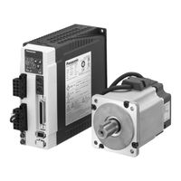
Panasonic Minas A4 Series Instruction Manual (366 pages)
AC Servo Motor and Driver
Brand:
Panasonic
| Category:
Controller
| Size: 7.72 MB
Table of Contents
[Before Using the Products]
9
Table of Contents
9
Safety Precautions
10
Maintenance and Inspection
14
Introduction
16
Check of the Motor Model
17
Check of the Combination of the Driver and the Motor
18
Parts Description
20
Motor
22
Console
23
Installation
24
Motor
26
Console
28
[Preparation]
29
Preparation
29
System Configuration and Wiring
30
Overall Wiring (Connecting Example of C-Frame, 3-Phase)
30
Overall Wiring (Connecting Example of E-Frame)
32
Driver and List of Peripheral Equipments
34
Wiring of the Main Circuit (a to D-Frame)
36
Wiring of the Main Circuit (E and F-Frame)
37
Wiring to the Connector, CN X6 (Connection to Encoder)
40
Wiring to the Connector, CN X3 and 4 (Connection to PC, Host Controller or Console)
42
Wiring to the Connector, CN X5 (Connection to Host Controller)
43
Timing Chart
44
Built-In Holding Brake
48
Dynamic Brake
50
Caution on Homing
52
Setup of Parameter and Mode
53
Outline of Parameter
53
How to Set
53
How to Connect
53
Composition and List of Parameters
54
Setup of Torque Limit
59
How to Use the Front Panel and Console
60
Setup with the Front Panel
60
Setup with the Console
60
Initial Status of the Front Panel Display(7 Segment LED)
61
Initial Status of the Console Display(7 Segment LED)
61
Structure of each Mode
62
Monitor Mode
65
Parameter Setup Mode
71
EEPROM Writing Mode
72
Auto-Gain Tuning Mode
73
Auxiliary Function Mode
75
Copying Function (Console Only)
81
[Connection and Setup of Position Control Mode]
83
Connection and Setup of Position Control Mode
83
Control Block Diagram of Position Control Mode
84
Wiring to the Connector, CN X5
85
Wiring Example to the Connector, CN X5
85
Interface Circuit
86
Input Signal and Pin No. of the Connector, CN X5
88
Output Signal and Pin No. of the Connector, CN X5
94
Connecting Example to Host Controller
98
Trial Run (JOG Run) at Position Control Mode
106
Inspection before Trial Run
106
Trial Run by Connecting the Connector, CN X5
106
Real-Time Auto-Gain Tuning
108
Outline
108
Applicable Range
108
How to Operate
108
Adaptive Filter
109
Parameters Which Are Automatically Set
109
Parameter Setup
110
Parameters for Functional Selection
110
Parameters for Adjustment of Time Constant of Gains and Filters
113
Parameters for Auto-Gain Tuning
114
Parameters for Adjustment (2Nd Gain Switching Function)
117
Parameters for Position Control
118
Parameters for Velocity/Torque Control
122
Parameters for Sequence
122
[Connection and Setup of Velocity Control Mode]
127
Connection and Setup of Velocity Control Mode
127
Control Block Diagram of Velocity Control Mode
128
Wiring to the Connector, CN X5
129
Wiring Example to the Connector, CN X5
129
Interface Circuit
130
Input Signal and Pin No. of the Connector, CN X5
132
Output Signal and Pin No. of the Connector, CN X5
137
Trial Run (JOG Run) at Velocity Control Mode
140
Inspection before Trial Run
140
Trial Run by Connecting the Connector, CN X5
141
Real-Time Auto-Gain Tuning
142
Outline
142
Applicable Range
142
How to Operate
142
Adaptive Filter
143
Parameters Which Are Automatically Set
143
Parameter Setup
144
Parameters for Functional Selection
144
Parameters for Adjustment of Time Constant of Gains and Filters
148
Parameters for Auto-Gain Tuning
149
Parameters for Adjustment (2Nd Gain Switching Function)
151
Parameters for Position Control
153
Parameters for Velocity/Torque Control
154
Parameters for Sequence
157
[Connection and Setup of Torque Control Mode]
161
Parameters for Velocity/Torque Control
161
Control Block Diagram of Torque Control Mode
162
Wiring to the Connector, CN X5
163
Wiring Example to the Connector, CN X5
163
Interface Circuit
164
Input Signal and Pin No. of the Connector, CN X5
166
Output Signal and Pin No. of the Connector, CN X5
170
Trial Run (JOG Run) at Torque Control Mode
173
Inspection before Trial Run
173
Trial Run by Connecting the Connector, CN X5
173
Real-Time Auto-Gain Tuning
174
Outline
174
Applicable Range
174
How to Operate
174
Parameters Which Are Automatically Set up
175
Parameter Setup
176
Parameters for Functional Selection
176
Parameters for Adjustment of Time Constant of Gains and Filters
179
Parameters for Auto-Gain Tuning
180
Parameters for Adjustment (2Nd Gain Switching Function)
181
Parameters for Position Control
183
Parameters for Velocity/Torque Control
185
Parameters for Sequence
187
[Full-Closed Control Mode]
191
Parameters for Velocity/Torque Control
191
Outline of Full-Closed Control
192
What Is Full-Closed Control
192
Control Block Diagram of Full-Closed Control Mode
193
Wiring to the Connector, CN X5
194
Wiring Example to the Connector, CN X5
194
Interface Circuit
195
Input Signal and Pin No. of the Connector, CN X5
197
Output Signal and Pin No. of the Connector, CN X5
203
Connection to the Connector, CN X7
206
Connector, CN X7
206
Wiring to the External Scale, Connector, CN X7
207
Real-Time Auto-Gain Tuning
208
Outline
208
Applicable Range
208
How to Operate
208
Adaptive Filter
209
Parameters Which Are Automatically Set up
209
Parameter Setup
210
Parameters for Functional Selection
210
Parameters for Adjustment of Time Constant of Gains and Filters
213
Parameters for Auto-Gain Tuning
214
Parameters for Adjustment (2Nd Gain Switching Function)
216
Parameters for Position Control
218
Parameters for Velocity/Torque Control
222
Parameters for Sequence
222
Parameters for Full-Closed
226
[Adjustment]
227
Adjustment
227
Gain Adjustment
228
Real-Time Auto-Gain Tuning
230
Fit-Gain Function
233
Adaptive Filter
236
Normal Auto-Gain Tuning
238
Release of Automatic Gain Adjusting Function
241
Manual Auto-Gain Tuning (Basic)
242
Adjustment in Position Control Mode
243
Adjustment in Velocity Control Mode
243
Adjustment in Torque Control Mode
244
Adjustment in Full-Closed Control Mode
244
Gain Switching Function
245
Suppression of Machine Resonance
248
Automatic Gain Setup Function
250
Manual Auto-Gain Tuning (Application)
251
Instantaneous Speed Observer
251
Damping Control
252
[When in Trouble]
253
When in Trouble
253
When in Trouble
254
What to Check
254
Protective Function (What Is Error Code ?)
254
Protective Function (Details of Error Code)
255
Troubleshooting
262
Motor Does Not Run
262
Unstable Rotation (Not Smooth)/Motor Runs Slowly Even with Speed Zero at Velocity Control Mode
263
Positioning Accuracy Is Poor
264
Origin Point Slips
265
Abnormal Noise or Vibration
265
Overshoot/Undershoot, Overheating of the Motor (Motor Burn-Out)
266
Motor Speed Does Not Reach to the Setup/Motor Revolution (Travel) Is too Large or Small
266
Parameter Returns to Previous Setup
266
Display of "Communication Port or Driver Cannot be Detected" Appears on the Screen While Using the PANATERM
266
[Supplement]
267
Absolute System
268
Outline of the Setup Support Software, PANATERM
278
Communication
280
Division Ratio for Parameters
308
Conformity to EC Directives and UL Standards
310
Options
314
Recommended Components
325
Dimensions (Driver)
326
Dimensions (Motor)
329
Permissible Load at Output Shaft
344
Motor Characteristics (S-T Characteristics)
345
Motor with Gear Reducer
351
Dimensions (Motor with Gear Reducer)
352
Permissible Load at Output Shaft (Motor with Gear Reducer)
354
Motor Characteristics (S-T Characteristics)/Motor with Gear Reducer
355
Block Diagram of Driver
356
Block Diagram of Driver by Control Mode
358
Specifications (Driver)
360
Homing with "Hit & Stop" and "Press & Hold" Control
362
Advertisement
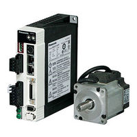
Panasonic Minas A4 Series Technical Reference (26 pages)
AC Servo Motor & Driver
Brand:
Panasonic
| Category:
Servo Drives
| Size: 1.43 MB
Table of Contents
Table of Contents
2
Introduction
3
Check of the Driver Model
3
Check of the Motor Model
3
Installation
4
Driver
4
Motor
5
Console
6
System Configuration and Wiring
7
Overall Wiring (Connecting Example of C-Frame, 3-Phase)
7
Overall Wiring (Connecting Example of E-Frame)
8
Driver and List of Applicable Peripheral Equipments
9
Wiring of the Main Circuit (a to D-Frame)
10
Wiring of the Main Circuit (E and F-Frame)
10
Wiring Method to Connector (a to D-Frame)
11
Wiring to the Connector, CN X6
13
Parameter
15
Outline of Parameter
15
How to Set
15
Setup with the Front Panel
15
Outline of PANATERM
16
Setup with the Console
16
How to Connect
16
Composition and List of Parameters
17
Protective Functions
20
Protective Function (What Is Error Code ?)
20
Maintenance and Inspections . B38
21
Conformity to EC Directives and UL Standards
22
Composition of Peripheral Equipments
22
Conformity to UL Standards
24
Built-In Holding Brake
24
Dynamic Brake
25
Check of the Combination of the Driver and the Motor
26
Panasonic Minas A4 Series Connection Manual (5 pages)
servo drive
Brand:
Panasonic
| Category:
Controller
| Size: 0.24 MB
Advertisement
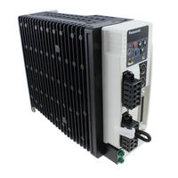
Panasonic Minas A4 Series Features (1 page)
A (Ace) Servo for the Next Generation
Brand:
Panasonic
| Category:
Power Supply
| Size: 0.37 MB
Advertisement
Related Products
Panasonic MINAS A3 Series
Panasonic MINAS A4P Series
Panasonic AW-PS550E
Panasonic MINAS-E Series
Panasonic A406
Panasonic A47
Panasonic MINAS A4-series
Panasonic Advidia A-46-F
Panasonic Advidia A-46-FW
Panasonic A4S
Panasonic Categories
Camcorder
Air Conditioner
TV
Digital Camera
Cordless Telephone
More Panasonic Manuals
Login
Sign In
OR
Sign in with Facebook
Sign in with Google
Upload manual
Upload from disk
Upload from URL