Sign In
Upload
Manuals
Brands
Panasonic Manuals
Air Conditioner
PA-26MA1XPK
Panasonic PA-26MA1XPK Manuals
Manuals and User Guides for Panasonic PA-26MA1XPK. We have
1
Panasonic PA-26MA1XPK manual available for free PDF download: Service Manual
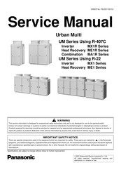
Panasonic PA-26MA1XPK Service Manual (643 pages)
Using R-407C / R-22
Brand:
Panasonic
| Category:
Air Conditioner
| Size: 16.94 MB
Table of Contents
Table of Contents
2
Introduction
14
Safety Cautions
14
Survey of Possible um Outdoor Units
18
Survey of Possible um Indoor Units
19
Nomenclature
20
80#6Hulhv#8Vlqj#5055
22
Outline of System
25
MX1 Series
25
Changes in "MX1" Series Functions / Parts
26
ME1 Series
28
3Duw#5 )Xqfwlrq111111111111111111111111111111111111111111111111111111111111111111111111111111
30
Function
31
Outdoor Unit Refrigerant System Diagram
31
List of Safety Devices and Functional Parts Setting Values
39
Flow of Refrigerant in each Operation Mode (ME1 Series)
41
Outline of Control (ME1 Series)
46
Safety for Restart
48
Equalized Oil Level Operation (Equalized Oil Level between Twin Compressors)
51
Oil Return Operation
52
Defrost
54
Pressure Equalization Control (ME1 Series)
57
Frequency Limit Control by Pressure Equalization (ME1 Series)
58
Changeover Control (ME1 Series)
59
Pump down Residual Operation
60
Step down / Safety Control → Standby (Forced Thermostat OFF) → Stop Due to Malfunction
63
Control During Low Outdoor Air Temperature Cooling
66
Low Noise Control
68
Demand Control
69
Compressor Capacity Control
70
Te / Tc Setting
71
Gas Depletion Alarm
72
Drain Pump Control
73
Oil Temperature Sensor (8 and 10 Hp Only)
75
Louver Control for Preventing Ceiling Dirt
76
Thermostat Sensor in Remote Controller
77
Freeze Prevention
79
3Duw6
80
Test Operation
81
Procedure and Outline
81
When Power Is Turned on
83
Outdoor Unit PC Board Ass'y
84
Setting Modes (MX1 Series)
88
Setting Modes (ME1 Series)
94
Sequential Start
100
BMS Interface Adaptor for Outdoor Unit (MX1 Series)
101
BMS Interface Adaptor for Outdoor Unit (ME1 Series)
104
Cool / Heat Mode Selection (MX1 Series)
108
Cool / Heat Mode Switching (ME1 Series)
113
Low Noise / Demand Operation (MX1 Series)
115
Low Noise Operation (ME1 Series)
117
Demand Control (ME1 Series)
118
Wiring Check Operation
119
Indoor Unit PCB Ass'y
120
Remote Controllers (Wired and Wireless)
121
Control by Remote Controller (Double Remote Controllers, Group, Remote)
127
Indoor Field Setting
129
Centralised Control Group No. Setting
131
Setting of Master Remote Controller
133
Centralised Control Devices
135
Central Remote Controller (CZ-01ESM11P)
137
Unified ON/OFF Controller (CZ-01ANA11P)
144
Schedule Timer (CZ-01ESW11P)
147
Combining Different Types of Centralised Control Devices
151
3Duw#7 7Urxeohvkrrwlqj 1111111111111111111111111111111111111111111111111111111111111
156
Operation Flowcharts
158
Indoor Unit Operation Flowchart
158
Outdoor Unit Operation Flowchart
163
Troubleshooting by Remote Controller
167
The INSPECTION / TEST Button
167
Self-Diagnosis by Wired Remote Controller
168
Self-Diagnosis by Wireless Remote Controller
169
Operation of the Remote Controller's Inspection / Test Operation Button
172
Remote Controller Service Mode
173
Remote Controller Self-Diagnosis Function
175
(Display of Malfunction Code)
175
Troubleshooting
177
Indoor Unit: Error of External Protection Device
177
Indoor Unit: PC Board Defect
178
Indoor Unit: Malfunction of Drain Level Control System (33H)
179
Indoor Unit: Fan Motor (M1F) Lock, Overload
180
Indoor Unit: Malfunction of Swing Flap Motor (M1S)
181
Indoor Unit: Malfunction of Moving Part of Electronic Expansion Valve (Y1E)
182
Indoor Unit: Drain Level above Limit
183
Indoor Unit: Malfunction of Capacity Determination Device
184
Indoor Unit: Malfunction of Thermistor (R2T) for Liquid Pipe
185
Indoor Unit: Malfunction of Thermistor (R3T) for Gas Pipes
186
Indoor Unit: Malfunction of Thermistor (R1T) for Air Inlet
187
In Remote Controller
188
Outdoor Unit: Actuation of Safety Device
189
Outdoor Unit: PC Board Defect
190
Outdoor Unit: Actuation of High Pressure Switch
191
Outdoor Unit: Actuation of Low Pressure Switch
192
Outdoor Unit: Malfunction of Moving Part of
193
Electronic Expansion Valve (Y1E)
193
Outdoor Unit: Abnormal Discharge Pipe Temperature
194
Outdoor Unit: Malfunction of Thermistor (R1T) for Outdoor Air
195
Outdoor Unit: Malfunction of Discharge Pipe Thermistor (R3T)
196
Outdoor Unit: Malfunction of Thermistor (R4T) for Suction Pipe
197
Outdoor Unit: Malfunction of Thermistor (R2T) for Heat Exchanger
198
Outdoor Unit: Malfunction of Discharge Pipe Pressure Sensor
199
Outdoor Unit: Malfunction of Suction Pipe Pressure Sensor
200
Outdoor Unit: Malfunction of Oil Temperature Thermistor (R5T)
201
Low Pressure Drop Due to Refrigerant Shortage or Electronic Expansion Valve Failure
202
Negative Phase, Open Phase
203
Malfunction of Transmission between Indoor Units
204
Malfunction of Transmission between Remote Controller and Indoor Unit
205
Malfunction of Transmission between Outdoor Units
206
Malfunction of Transmission between Master and Slave Remote Controllers
207
Malfunction of Transmission between Indoor and Outdoor Units in the same System
208
Excessive Number of Indoor Units
209
Address Duplication of Central Remote Controller
210
Refrigerant System Not Set, Incompatible Wiring/Piping
211
Malfunction of System, Refrigerant System Address Undefined
212
Failure Diagnosis for Inverter System
213
Points of Diagnosis
213
How to Use the Monitor Switch on the Inverter PC Board
214
Troubleshooting (Inverter)
215
Outdoor Unit: Malfunction of Inverter Radiating Fin Temperature Rise
215
Outdoor Unit: Inverter Instantaneous Over-Current
216
Outdoor Unit: Inverter Thermostat Sensor, Compressor Overload
217
Outdoor Unit: Inverter Stall Prevention, Compressor Lock
218
Outdoor Unit: Malfunction of Transmission between Inverter and Control PC Board
219
Power Supply Insufficient or Instantaneous Failure
220
Outdoor Unit: Inverter Over-Ripple Protection
221
Outdoor Unit: Malfunction of Inverter Radiating Fin Temperature Rise Sensor
222
Troubleshooting (OP: Central Remote Controller)
223
Malfunction of Transmission between Central Remote Controller and Indoor Unit
223
PC Board Defect
224
Malfunction of Transmission between Optional Controllers for Centralised Control
225
Improper Combination of Optional Controllers for Centralised Control
226
Address Duplication, Improper Setting
227
Troubleshooting (OP: Schedule Timer)
228
Malfunction of Transmission between Central Remote Controller and Indoor Unit
228
PC Board Defect
229
Malfunction of Transmission between Optional Controllers for Centralised Control
230
Improper Combination of Optional Controllers for Centralised Control
231
Address Duplication, Improper Setting
232
Troubleshooting (OP: Unified ON/OFF Controller)
233
Operation Lamp Blinks
233
Display "Under Host Computer Integrate Control" Blinks (Repeats Single Blink)
234
Display "Under Host Computer Integrate Control" Blinks (Repeats Double Blink)
236
80#6Hulhv#8Vlqj#5073
238
Introduction
241
Introduction of the Series
241
Outline
242
MX1R Series
242
ME1R Series (Heat Recovery)
243
Allowed Range of Indoor Unit and HR Box Connection
244
Function
247
Outdoor Unit Refrigerant System Diagram
247
List of Safety Devices and Functional Parts Setting Values
255
Flow of Refrigerant in each Operation Mode (ME1R Series)
257
Outline of Control (ME1R Series)
262
Safety for Restart
264
Equalized Oil Level Operation (Equalized Oil Level between Twin Compressors)
266
Oil Return Operation
267
Defrost
269
Pressure Equalization Control (ME1R Series)
272
Frequency Limit Control by Pressure Equalization (ME1R Series)
273
Changeover Control (ME1R Series)
274
Pump down Residual Operation
275
Step down / Safety Control → Standby (Forced Thermostat OFF) → Stop Due to Malfunction
276
Stop Due to Malfunction
276
Control During Low Outdoor Air Temperature Cooling
279
Low Noise Control
281
Demand Control
282
Compressor Capacity Control
283
Te / Tc Setting
284
Gas Depletion Alarm
285
Drain Pump Control
286
Oil Temperature Sensor (8 and 10 Hp Only)
288
Louver Control for Preventing Ceiling Dirt
289
Thermostat Sensor in Remote Controller
290
Freeze Prevention
292
Test Operation
295
Procedure and Outline
295
When Power Is Turned on
297
Outdoor Unit PC Board Ass'y
298
Setting Modes (MX1R Series)
302
Setting Modes (ME1R Series)
309
Sequential Start
315
BMS Interface Adaptor for Outdoor Unit (MX1R Series)
316
BMS Interface Adaptor for Outdoor Unit (ME1R Series)
319
Cool / Heat Mode Selection (MX1R Series)
323
Cool / Heat Mode Switching (ME1R Series)
330
Low Noise / Demand Operation (MX1R Series)
332
Low Noise Operation (ME1R Series)
334
Demand Control (ME1R Series)
335
Wiring Check Operation
336
Indoor Field Setting
337
Centralised Control Group No. Setting
339
Setting of Master Remote Controller
341
Operation Flowcharts
346
Indoor Unit Operation Flowchart
346
Outdoor Unit Operation Flowchart
351
Troubleshooting by Remote Controller
355
The INSPECTION / TEST Button
355
Self-Diagnosis by Wired Remote Controller
356
Self-Diagnosis by Wireless Remote Controller
357
Operation of the Remote Controller's Inspection / Test Operation Button
360
Remote Controller Service Mode
361
Remote Controller Self-Diagnosis Function
363
(Display of Malfunction Code)
363
Troubleshooting
365
Indoor Unit: Error of External Protection Device
365
Indoor Unit: PC Board Defect
366
Indoor Unit: Malfunction of Drain Level Control System (33H)
367
Indoor Unit: Fan Motor (M1F) Lock, Overload
368
Indoor Unit: Malfunction of Swing Flap Motor (M1S)
369
Indoor Unit: Malfunction of Moving Part of Electronic Expansion Valve (Y1E)
370
Indoor Unit: Drain Level above Limit
371
Indoor Unit: Malfunction of Capacity Determination Device
372
Indoor Unit: Malfunction of Thermistor (R2T) for Liquid Pipe
373
Indoor Unit: Malfunction of Thermistor (R3T) for Gas Pipes
374
Indoor Unit: Malfunction of Thermistor (R1T) for Air Inlet
375
Indoor Unit: Malfunction of Thermostat Sensor in Remote Controller
376
Outdoor Unit: Actuation of Safety Device
377
Outdoor Unit: PC Board Defect
378
Outdoor Unit: Actuation of High Pressure Switch
379
Outdoor Unit: Actuation of Low Pressure Switch
380
Outdoor Unit: Malfunction of Moving Part of Electronic Expansion Valve (Y1E)
381
Electronic Expansion Valve (Y1E)
381
Outdoor Unit: Abnormal Discharge Pipe Temperature
382
Outdoor Unit: Malfunction of Thermistor (R1T) for Outdoor Air
383
Outdoor Unit: Malfunction of Discharge Pipe Thermistor (R3T)
384
Outdoor Unit: Malfunction of Thermistor (R4T) for Suction Pipe
385
Outdoor Unit: Malfunction of Thermistor (R2T) for Heat Exchanger
386
Outdoor Unit: Malfunction of Discharge Pipe Pressure Sensor
387
Outdoor Unit: Malfunction of Suction Pipe Pressure Sensor
388
Outdoor Unit: Malfunction of Oil Temperature Thermistor (R5T)
389
Low Pressure Drop Due to Refrigerant Shortage or Electronic Expansion Valve Failure
390
Negative Phase, Open Phase
391
Malfunction of Transmission between Indoor Units
392
Malfunction of Transmission between Remote Controller and Indoor Unit
393
Malfunction of Transmission between Outdoor Units
394
Malfunction of Transmission between Master and Slave Remote Controllers
395
Malfunction of Transmission between Indoor and Outdoor Units in the same System
396
Excessive Number of Indoor Units
397
Address Duplication of Central Remote Controller
398
Refrigerant System Not Set, Incompatible Wiring/Piping
399
Malfunction of System, Refrigerant System Address Undefined
400
Failure Diagnosis for Inverter System
401
Points of Diagnosis
401
How to Use the Monitor Switch on the Inverter PC Board
402
Troubleshooting (Inverter)
403
Outdoor Unit: Malfunction of Inverter Radiating Fin Temperature Rise
403
Outdoor Unit: Inverter Instantaneous Over-Current
404
Outdoor Unit: Inverter Thermostat Sensor, Compressor Overload
405
Outdoor Unit : Inverter Stall Prevention, Compressor Lock
406
Outdoor Unit: Malfunction of Transmission between Inverter and Control PC Board
407
Power Supply Insufficient or Instantaneous Failure
408
Outdoor Unit: Inverter Over-Ripple Protection
409
Outdoor Unit: Malfunction of Inverter Radiating Fin Temperature Rise Sensor
410
Troubleshooting (OP: Central Remote Controller)
411
Malfunction of Transmission between Central Remote Controller and Indoor Unit
411
PC Board Defect
412
Malfunction of Transmission between Optional Controllers for Centralised Control
413
Improper Combination of Optional Controllers for Centralised Control
414
Address Duplication, Improper Setting
415
Troubleshooting (OP: Schedule Timer)
416
Malfunction of Transmission between Central Remote Controller and Indoor Unit
416
PC Board Defect
417
Malfunction of Transmission between Optional Controllers for Centralised Control
418
Improper Combination of Optional Controllers for Centralised Control
419
Address Duplication, Improper Setting
420
Troubleshooting (OP: Unified ON/OFF Controller)
421
Operation Lamp Blinks
421
Display "Under Host Computer Integrate Control" Blinks (Repeats Single Blink)
422
Display "Under Host Computer Integrate Control" Blinks (Repeats Double Blink)
424
80#6Hulhv#8Vlqj#5073
426
Rpelqdwlrq#0;45#6Hulhv# 11111111111111111111111
426
Product Outline
429
Year 2001 Models Using New Refrigerant
429
Outline of New Series Products
430
Model Configuration and Combination
432
Outdoor Unit Refrigerant System Diagram
435
Flow of Refrigerant in each Operating Mode
438
List of Safety Device and Function Parts Setting Value
442
Outdoor Unit
442
Indoor Unit
443
Outline of Control
446
Outdoor Unit
446
Indoor Unit
466
Test Operation
473
Procedure and Outline
473
Operation When Power Is Turned on
475
Outdoor Unit PC Board Ass'y
476
Setting Modes
478
Cool / Heat Mode Selection
485
Low Noise Operation
490
Demand Control
491
Sequential Start
492
Wiring Check Operation
493
Additional Refrigerant Charge Operation
494
Refrigerant Recovery Mode
495
Indoor Field Setting
496
Centralised Control Group No. Setting
498
Contents of Control Modes
500
3Duw#7 7Urxeohvkrrwlqj 1111111111111111111111111111111111111111111111111111111111111 7;4
502
Operation Flowcharts
504
Indoor Unit Operation Flowchart
504
Troubleshooting by Remote Controller
509
The INSPECTION / TEST Button
509
Self-Diagnosis by Wired Remote Controller
510
Self-Diagnosis by Wireless Remote Controller
511
Operation of the Remote Controller's Inspection / Test Operation Button
514
Remote Controller Service Mode
515
Remote Controller Self-Diagnosis Function
517
(Display of Malfunction Code)
517
Troubleshooting
519
Indoor Unit: Error of External Protection Device
519
Indoor Unit: PC Board Defect
520
Indoor Unit: Malfunction of Drain Level Control System (33H)
521
Indoor Unit: Fan Motor (M1F) Lock, Overload
522
Indoor Unit: Malfunction of Swing Flap Motor (M1S)
523
Indoor Unit: Malfunction of Moving Part of
524
Electronic Expansion Valve (Y1E)
524
Indoor Unit: Drain Level above Limit
525
Indoor Unit: Malfunction of Capacity Determination Device
526
Indoor Unit: Malfunction of Thermistor (R2T) for Liquid Pipe
527
Indoor Unit: Malfunction of Thermistor (R3T) for Gas Pipes
528
Indoor Unit: Malfunction of Thermistor (R1T) for Air Inlet
529
Indoor Unit: Malfunction of Thermostat Sensor in Remote Controller
530
Outdoor Unit: Actuation of Safety Device
531
Outdoor Unit: PC Board Defect
532
Outdoor Unit: Actuation of High Pressure Switch
533
Outdoor Unit: Actuation of Low Pressure Switch
534
Outdoor Unit: Malfunction of Moving Part of
535
Electronic Expansion Valve (Y1E)
535
Outdoor Unit: Abnormal Discharge Pipe Temperature
536
Outdoor Unit: Malfunction of Thermistor (R1T) for Outdoor Air
537
Outdoor Unit: Malfunction of Discharge Pipe Thermistor (R3T)
538
Outdoor Unit: Malfunction of Thermistor (R4T) for Suction Pipe
539
Outdoor Unit: Malfunction of Thermistor (R2T) for Heat Exchanger
540
Outdoor Unit: Malfunction of Discharge Pipe Pressure Sensor
541
Outdoor Unit: Malfunction of Suction Pipe Pressure Sensor
542
Low Pressure Drop Due to Refrigerant Shortage or Electronic Expansion Valve Failure
543
Negative Phase, Open Phase
544
Malfunction of Transmission between Indoor Units
545
Malfunction of Transmission between Remote Controller and Indoor Unit
546
Malfunction of Transmission between Outdoor Units
547
Malfunction of Transmission between Master and Slave Remote Controllers
548
Malfunction of Transmission between Indoor and Outdoor Units in the same System
549
Excessive Number of Indoor Units
550
Address Duplication of Central Remote Controller
551
Refrigerant System Not Set, Incompatible Wiring/Piping
552
Malfunction of System, Refrigerant System Address Undefined
553
Failure Diagnosis for Inverter System
554
Points of Diagnosis
554
How to Use the Monitor Switch on the Inverter PC Board
555
Troubleshooting (Inverter)
556
Outdoor Unit: Malfunction of Inverter Radiating Fin Temperature Rise
556
Outdoor Unit: Malfunction of Inverter Radiating
556
Fin Temperature Rise
556
Outdoor Unit: Inverter Instantaneous Over-Current
557
Outdoor Unit: Inverter Thermostat Sensor, Compressor Overload
558
Outdoor Unit: Inverter Stall Prevention, Compressor Lock
559
Outdoor Unit: Malfunction of Transmission between Inverter and Control PC Board
560
Outdoor Unit: Malfunction of Transmission
560
Between Inverter and Control PC Board
560
Power Supply Insufficient or Instantaneous Failure
561
Outdoor Unit: Inverter Over-Ripple Protection
562
Fin Temperature Rise Sensor
563
Outdoor Unit: Malfunction of Inverter Radiating Fin Temperature Rise Sensor
563
Troubleshooting (OP: Central Remote Controller)
564
Malfunction of Transmission between Central Remote Controller and Indoor Unit
564
PC Board Defect
565
Malfunction of Transmission between Optional Controllers for Centralised Control
566
Improper Combination of Optional Controllers for Centralised Control
567
Address Duplication, Improper Setting
568
Troubleshooting (OP: Schedule Timer)
569
Malfunction of Transmission between Central Remote Controller and Indoor Unit
569
PC Board Defect
570
Malfunction of Transmission between Optional Controllers for Centralised Control
571
Improper Combination of Optional Controllers for Centralised Control
572
Address Duplication, Improper Setting
573
Troubleshooting (OP: Unified ON/OFF Controller)
574
Operation Lamp Blinks
574
Display "Under Host Computer Integrate Control" Blinks (Repeats Single Blink)
575
Display "Under Host Computer Integrate Control" Blinks (Repeats Double Blink)
577
Backup and Emergency Operation
579
Pump down Operation
581
Sshqgl
582
Wiring Diagrams (Outdoor Unit)
583
MX1 Series
583
ME1 Series (Heat Recovery)
585
MX1R Series
587
ME1R Series (Heat Recovery)
589
MA1R Series (Combination)
591
Wiring Diagrams (Indoor Unit)
593
2-Way Cassette Type
593
4-Way Cassette Type
595
Corner Type
596
Built-In Type
597
Ducted Type
599
Ceiling Type
601
Wall Type
602
Floor Standing Type / Concealed Floor Standing Type
603
Small Duct Type
604
Characteristics
605
R407C Characteristics
605
Thermistor Resistance / Temperature Characteristics
606
Pressure Sensor
608
Method of Replacing the Inverter's Power Transistors and Diode Modules
609
Precaution
611
PC Boards and Remote Controller's Mode no
611
Typical Wiring Mistakes
612
Interface Adaptor
619
BMS Interface Adaptor for Unified Group (KRP2A51·52)
619
BMS Interface Adaptor for Individual and Unified Control (KRP4A51 / KRP4A52 / KRP4A53)
624
Signal Output Adaptor PCB for Optional Accessory (KRP1B61 / KRP1B2 / KRP1B3)
627
Interface Adaptor for Urban Split Series (CZ-102AP11P)
629
Interface Adaptor for Other Air Conditioners (CZ-103AP11P)
631
BMS Interface Adaptor for Outdoor Units (DTA104A51 · DTA104A52)
634
BMS Interface Adaptor (DCS302A52)
637
Precautions in Servicing the Models with New-Type Refrigerant
641
Tools Required
641
Notes for Work Procedures
642
Advertisement
Advertisement
Related Products
PANASONIC PA-26MX3XPQ
PANASONIC PA-26ME3XPQ
PANASONIC PA-20MX3XPQ
PANASONIC PA-22MX3XPQ
PANASONIC PA-24MX3XPQ
PANASONIC PA-28MX3XPQ
PANASONIC PA-22ME3XPQ
PANASONIC PA-24ME3XPQ
PANASONIC PA-28ME3XPQ
Panasonic PA-20MA1XPK
Panasonic Categories
Camcorder
Air Conditioner
TV
Digital Camera
Cordless Telephone
More Panasonic Manuals
Login
Sign In
OR
Sign in with Facebook
Sign in with Google
Upload manual
Upload from disk
Upload from URL