Sign In
Upload
Manuals
Brands
Samsung Manuals
UPS
9395P
Samsung 9395P Power Management System Manuals
Manuals and User Guides for Samsung 9395P Power Management System. We have
1
Samsung 9395P Power Management System manual available for free PDF download: Installation Manual
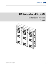
Samsung 9395P Installation Manual (129 pages)
Brand:
Samsung
| Category:
UPS
| Size: 6.7 MB
Table of Contents
Important Safety Instructions
5
General Instructions
6
Safety Precautions
6
Personnel and Equipment Warnings
7
Dangerous Voltages
7
Lock Out/Tag out Guidelines
8
General Warnings
8
Table of Contents
11
Table of Contents
12
Tables
13
Figures
14
About this Manual
19
Purpose
19
Target Audience
19
Organization
19
Revision History
20
Acronyms and Abbreviations
21
Product Description
22
Major Components
22
Battery Module (Type a / Type B)
23
Figure 2-1: Battery Module Type a
23
Figure 2-2: Battery Module Type B
24
SMU (String Management Unit)
25
SMPS Assembly (Type a / Type B)
26
Figure 2-4: SMPS Assembly Type a
26
Figure 2-5: SMPS Assembly Type B
26
Rack Frame
27
Figure 2-6: Rack Frame
27
Installing the Product
28
Grounding the Battery System
28
Arc Flash Calculations
29
Installation Procedure
30
Figure 3-1: Installation Procedure
30
Table 3-1: Estimated Time for Installation (Based on 136S 3P Installation)
31
Preparation Stage-Procedure
32
Preparation Stage-Unpacking
33
Table 3-2: Parts for 136S 3P Rack
33
Figure 2-3: SMU
33
Preparation Stage-Ground Wire and Tools
34
Ground Wires
34
Ground Wire Fasteners
34
Rack Fasteners (Anchors)
34
Multiple Rack Fasteners
34
Table 3-3: Ground Wire Specifications
34
Table 3-4: Ground Wire Fastener Specification
34
Table 3-5: Rack Fastener Specifications
34
Table 3-6: Rack Fastener Specifications (Side by Side)
34
Preparation Stage-Recommended Tools/Instruments
35
Table 3-7: Recommended Tools and Instruments
35
Preparation Stage-Visual Inspection
37
Inspection of the Rack Frame
37
Inspection of the Modules
37
Inspecting the SMU
37
Table 3-8: Module Voltage and Internal Impedance
37
Inspecting the SMPS Assembly
38
Rack Anchoring Stage
39
Table 3-9: Rack Clearance Distances
39
Figure 3-2: Clearance Distance for Single Rack Frame
40
Figure 3-3: Clearance Distance for Multiple Rack Frames Installed Side-By-Side
40
Figure 3-4: Clearance Distance for Multiple Rack Frames Installed Side-By-Side and Rear-To-Rear
41
Figure 3-5: Front Panel Screws (Eight)
41
Figure 3-6: Front Panel Hooks (Four)
42
Figure 3-7: Side Panel Screws (Six)
42
Figure 3-8: Side Panel Hooks (Four)
43
Figure 3-9: Rear Panel Screws (Eight)
43
Figure 3-10: Rear Panel Hooks (Four)
44
Figure 3-11: Rack Anchoring Points (4 EA)
44
Figure 3-12: Holes on the Sides of the Rack (Six)
45
Figure 3-13: Reattaching the Side Panels (Four Hooks and Six Screws for each Panel)
46
Figure 3-14: Reattaching the Rear Panels
47
Rack Installation Stage
48
Front Door Removal
49
Figure 3-15: Front Door Ajar
49
Figure 3-16: Removing the Earth Cable
49
Figure 3-17: Removing the Front Door
50
Figure 3-18: All Doors and Front Panels Removed
50
SMU and SMPS Assembly Installation
51
Figure 3-19: Inserting SMU
51
Figure 3-20: Attaching a SMU to a Rack Frame
51
Figure 3-21: Ground Cable Connection to the SMU
52
Figure 3-22: Inserting SMPS Assembly
53
Figure 3-23: Attaching the SMPS Assembly
53
Figure 3-24: Ground Cable Connection to the SMPS Assembly
54
Battery Module Installation
55
Figure 3-25: Insertion of Modules on the Ninth Shelf from the Bottom
55
Figure 3-26: Battery Module Arrangement on the Eighth Shelf
56
Figure 3-27: Battery Module Arrangement
56
Figure 3-28 : Module Number
57
Figure 3-29: Insertion of Modules on 1St Shelf
57
Fuse-Busbar Assembly
58
Figure 3-30: Rack Fuse Busbar Assembly
58
Figure 3-31: Rack Fuse Busbar Assembly (Fuse Cover)
58
Figure 3-32: Fuse Busbar Left Assembly
59
Figure 3-33: Fuse Busbar Left Assembly (Fuse Cover)
59
Figure 3-34: Fuse Busbar Right Assembly
60
Figure 3-35: Fuse Busbar Right Assembly (Fuse Cover)
60
Busbar Installation
61
Figure 3-36: Copper Busbar Appearance
62
Figure 3-37: Conductive Grease on Busbar
62
Figure 3-38: Contact Resistance Probe Points (Battery Module Terminal to Busbar)
63
Figure 3-39: Removing the Module #1'S Cover and SMU B- Terminal Cover
64
Figure 3-40: Connect SMU B- and Module #1 B
64
Figure 3-41: Restore Smu's B- Terminal
65
Figure 3-42: Remove Battery Module #2'S Front Cover
65
Figure 3-43: Connect Battery Module #1 B+ and Battery Module #2 B
66
Figure 3-44: Reattach Battery Module #1'S Front Cover
66
Figure 3-45: Remove Battery Module #2'S Front Cover
67
Figure 3-46: Connect Battery Module #2 B+ and Battery Module #3 B
67
Figure 3-47: Reattach Battery Module #2'S Front Cover
68
Figure 3-48: Remove Battery Module #4'S Front Cover
68
Module and SMU Signal Cable Connection
97
SMPS Assembly and SMU Power Cable Connection
109
SMPS Assembly and SMU Signal Cable Connection
110
SMPS Assembly AC Input Connection
112
DC Link Cable Connection
118
AC Input Commissioning
121
BMS Configuration
122
Communication Check
122
Reinstall the Front Door
123
Reinstall the Front Panel
124
Switching on the MCCB
125
Advertisement
Advertisement
Related Products
Samsung 93PM
Samsung 9395C
Samsung 9395
Samsung 932BW - SyncMaster - 19" LCD Monitor
Samsung SyncMaster 933SN
Samsung 931BF - SyncMaster - 19" LCD Monitor
Samsung SyncMaster 930ND
Samsung SyncMaster 931BW PLUS
Samsung 930X5J
Samsung SyncMaster 931NWPlus
Samsung Categories
Cell Phone
Monitor
Microwave Oven
Air Conditioner
LCD TV
More Samsung Manuals
Login
Sign In
OR
Sign in with Facebook
Sign in with Google
Upload manual
Upload from disk
Upload from URL