Sign In
Upload
Manuals
Brands
Samsung Manuals
Air Conditioner
AG070KSVGNH
Samsung AG070KSVGNH Manuals
Manuals and User Guides for Samsung AG070KSVGNH. We have
1
Samsung AG070KSVGNH manual available for free PDF download: Service Manual
Samsung AG070KSVGNH Service Manual (142 pages)
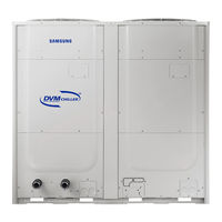
SYSTEM AIR CONDITIONER DVM CHILLER
Brand:
Samsung
| Category:
Air Conditioner
| Size: 5.4 MB
Table of Contents
Table of Contents
3
1 Precautions
5
Precautions for the Service
5
Precautions for the Static Electricity and PL
5
Precautions for the Safety
5
Precautions for Handling Refrigerant of the DVM CHILLER
6
Precautions for Welding the DVM CHILLER Pipe
6
2 Product Features and Specifications
7
Product Features
7
Major Advantages of Product
7
Control Logic
8
Changes in Comparison to DVM S
10
Structure of Product (H/P)
12
Product Specifications
13
Specifications
13
3 Disassembly and Reassembly
15
Necessary Tools
15
Disassembly and Reassembly
16
Ag042/056/070Ksv
16
Service Work of Main Parts
20
Water Pump
20
Temperature Sensor & Pressure Sensor in the Water Pipe Side
22
Plate Type Heat Exchanger PHE
24
Reference Sheet
30
4 Troubleshooting
33
Check-Up Window Description
33
Service Operation
34
Special Operation
34
DVM Chiller EEPROM Code Table by Models
37
Option Code by Model Classification
37
Number Display Method
38
Appropriate Measures for Symptoms
42
Reversed Phase / no Phase Check (Outdoor Unit with 3 Phase Power)
42
Main PCB Has no Power Phenomenon
44
Communication Error between Hydro and Outdoor Unit During Tracking
45
Communication Error between Indoor and Outdoor Unit after Tracking
47
Internal Communication Error of the Outdoor Unit C-Box
48
Internal PCB Communication Error of the Outdoor Unit C-Box
49
Outdoor Temperature Sensor Error
51
COND out Temperature Sensor Error (Open / Short)
52
Outdoor Unit COND out Sensor Breakaway Error
53
Compressor Discharge or TOP 1/2 Temperature Sensor Error
54
Compressor Discharge or TOP Temperature Sensor Breakaway Error
55
E269 : Suction Temperature Sensor Breakaway Error
56
High Pressure Sensor Error (Open / Short)
57
Low Pressure Sensor Error (Open / Short)
58
Suction Temperature Sensor Error (Open / Short)
59
Liquid Pipe Temperature Sensor Error (Open / Short)
60
EVI in Temperature Sensor Error (Open / Short)
61
EVI out Temperature Sensor Error (Open / Short)
62
Suction-2 Temperature Sensor Error (Open / Short)
63
Measures of Other Outdoor Unit Error
64
E407 : COMP down Due to High Pressure Protection Control
65
E410 : COMP down Due to Low Pressure Protection Control
66
E416: Suspension of Starting Due to Compressor Discharge Temperature Sensor / TOP Temperature Sensor
67
3-Phase Input Wiring Error
68
E428: : Suspension of Starting by Abnormal Compression Ratio
69
EVI EEV Opening Error
70
Refrigerant Leakage Error
71
Prevention of Heating Operation Due to Outdoor Temperature
72
Fan Starting Error
73
Fan Lock Error
75
Momentary Blackout Error
76
Outdoor Fan Motor Overheating
77
Fan IPM Overheat Error
78
Compressor Starting Error
79
Inverter Overcurrent Error
81
Overvoltage / Low Voltage Error
84
DC Link Voltage Sensor Error
85
Fan Motor Overcurrent Error
86
Input / Output Current Sensor Error
88
Outdoor Fan PCB Overvoltage / Low Voltage Error
89
Hall IC (Fan) Error
90
Inverter Overheat Error
91
Option Setting Error of Outdoor Unit
92
Hydro Inlet Temperature Sensor (Tw1) Short/Open
93
Hydro Outlet Temperature Sensor (Tw2) Short/Open
94
Frozen Damage Error
95
Error When Freeze Prevention Comp off
96
Hydro Outlet Temperature Sensor Breakaway
97
Water Flow Error(Water Pressure Sensor or Flow Switch)
98
Error on Pump Magnetic Switch Malfunction
99
5 PCB Diagram and Parts List
100
Assy Pcb Main-Hydro
100
Assy Pcb Main
105
Assy Pcb Sub-Fan
106
ASSY PCB SUB-EMI (PF#8 H Power Model Only)
108
ASSY PCB SUB-EMI (PF #9 H Power Model Only)
110
Assy Pcb Main-Hub
111
Assy Pcb Inverter
115
Assy Pcb Sub-Comm
119
6 Wiring Diagram
120
DVM CHILLER Hydro Part Wiring Diagram(AG042/056/070KSVANH/EU)
120
DVM CHILLER Hydro Part Wiring Diagram(AG042/056/070KSVGNH/EU)
121
DVM CHILLER Inverter Control Part Wiring Diagram(AG042/056KSVANH/EU)
122
DVM CHILLER Inverter Control Part Wiring Diagram(AG070KSVANH/EU)
123
DVM CHILLER Inverter Control Part Wiring Diagram(AG042/056KSVGNH/EU)
124
DVM CHILLER Inverter Control Part Wiring Diagram(AG070KSVGNH/EU)
125
7 Cycle Diagram
126
8 Key Options
128
Setting Hydro Controller Option
128
How to Set Hydro Controller Option
130
Setting Inverter Controller Option
135
9 Trial Operation
140
Trial Operation for each CHILLER Unit
140
Advertisement
Advertisement
Related Products
Samsung AG070KSVANH
Samsung AG072MN4DKH/EU
Samsung AG072MN4PKH/EU
Samsung AG072MN4DKH
Samsung AG072MN4DEU
Samsung AG072MN4PKH
Samsung AG072MN4PEU
Samsung AG072AN4DKH
Samsung AG072AN4DEU
Samsung AG026TN1DKH
Samsung Categories
Cell Phone
Monitor
Microwave Oven
Air Conditioner
LCD TV
More Samsung Manuals
Login
Sign In
OR
Sign in with Facebook
Sign in with Google
Upload manual
Upload from disk
Upload from URL