Sign In
Upload
Manuals
Brands
Samsung Manuals
Air Conditioner
AM260FX A Series
Samsung AM260FX A Series Manuals
Manuals and User Guides for Samsung AM260FX A Series. We have
1
Samsung AM260FX A Series manual available for free PDF download: Service Manual
Samsung AM260FX A Series Service Manual (414 pages)
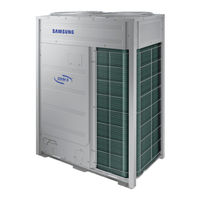
SYSTEM AIR CONDITIONER OUTDOOR UNIT
Brand:
Samsung
| Category:
Air Conditioner
| Size: 74.82 MB
Table of Contents
Table of Contents
2
Precautions
6
Precautions for the Service
6
Precautions for the Static Electricity and PL
6
Precautions for the Safety
6
Precautions for Handling Refrigerant for Air Conditioner
7
Precautions for Welding the Air Conditioner Pipe
7
Precautions for Additional Supplement of Air Conditioner Refrigerant
7
Other Precautions
7
Product Specifications
8
The Feature of Product
8
Feature
8
Changes in Comparison to Basic Model
10
Structure of Product ( Heat Pump: AMSSSSXVSSH Series )
13
Structure of Product (Heat Recovery: AMSSSSXVSSR Series )
14
Structure of Product (Power Supply for 460V, 60Hz, 3Φ : AMSSSSXVSSJS Series )
15
Structure of Product (DVM S WATER)
16
Structure of Product (Heat Pump AMSSSKXS Series)
17
Model Names of Indoor/Outdoor Unit
21
Outdoor Unit Combination
21
Indoor Unit
29
Outdoor Unit
30
Combination and Connection Ratio Limitation
36
Components and Feature
37
Product Specification
38
Outdoor Unit
38
Accessory and Option Specifications
69
Controller
69
Piping
72
Indoor
73
Controller & Control Accessory Compatibility
75
Indoor Units Accessory Compatibility
76
Disassembly and Reassembly
77
Necessary Tools
77
Disassembly and Reassembly
78
Checking the Device Condition
79
Removal Instructions for Panel
81
Disconnecting the Power Supply
85
Removal Instructions for Guard Fan
90
Removal Instructions for Fan and Motor
91
Removal Instructions for Compressor
96
Compressor Exchange Order
99
Removal Instructions for the Accumulator
101
Removal Instructions for Oil Separators
104
Removal Instructions for the Control PBA
106
Removal Instructions for the Hub PBA
108
Removal Instructions for the Control Panel Assy
111
Removal Instructions for the Inverter PBA
115
Removal Instructions for the Fan PBA
117
Removal Instructions for the DC Reactors and EMI PBA
118
Mcu
119
EEV Kit
120
Troubleshooting
121
Check-Up Window Description
121
Service Operation
122
Special Operation
122
DVM S Models EEPROM Code Table
132
Number Display Method
134
Appropriate Measures for Different Symptom
139
Outdoor Unit Operation Flow
139
Main PBA Has no Power Phenomenon
143
Communication Error between Indoor and Outdoor Units During Tracking
144
Communication Error between Indoor and Outdoor Units after Tracking
146
Communication Error between Main and Sub Unit of Outdoor Unit or between Outdoor Units
147
Internal Communication Error of the Outdoor Unit C-Box
148
Internal PBA Communication Error of the Outdoor Unit C-Box
149
MCU Branch Part Setup Error-Inconsecutive Connection with the Use of 2 Branch Parts
151
MCU Branch Part Setup Error-Repeated Setup for the same Address over 3 Times
152
MCU Branch Part Setup Error-Non-Installed Address Setup
153
Setup Error for MCU Branch Part-Setup Error for MCU Quantity Used
154
MCU Branch Part Setup Error-Overlapping Indoor Unit Address Setup
155
MCU Branch Part Setup Error_Set as Being Used Without Connection to an Indoor Unit
156
MCU Branch Part Setup Error-Connect an Indoor Unit to a Branch Part Not Being Used
157
MCU Branch Part Setup Error-Connect more Indoor Units than What Is Actually Set up in MCU
158
MCU/MCU Subcooler Entrance/Exit Sensor Error (Open/Short)
159
Outdoor Temperature Sensor Error
160
Cond out Temperature Sensor Error (Open/Short)
161
Outdoor Cond out Sensor Breakway Error
162
Compressor Discharge or TOP 1/2 Temperature Sensor Error
164
Compressor Discharge or TOP Temperature Sensor Breakway Error
165
High Pressure Sensor Error (Open/Short)
167
Low Pressure Sensor Error (Open/Short)
168
Suction Temperature Sensor Error (Open/Short)
169
Liquid Pipe Temperature Sensor Error (Open/Short)
170
EVI in Temperature Sensor Error (Open/Short)
171
EVI out Temperature Sensor Error (Open/Short)
172
Suction-2 Temperature Sensor Error (Open/Short)
173
Measures of Other Outdoor Unit Error
174
E416 : Suspension of Starting Due to Compressor Discharge Temperature Sensor/Top Temperature Sensor
179
3-Phase Input Wiring Error
180
EVI EEV Open Error
182
Refrigerant Leakage Error
183
Prevention of Heating/Cooling Operation Due to Outdoor Temperature
184
Prevention of Heating Refrigerant Charge Due to Outdoor Temperature
185
CCH Wire Breaking Error
186
Fan Motor Starting Error
188
Fan Motor Locking Error
190
Momentary Blackout Error
191
Outdoor Fan Motor Overheating
192
Fan PBA IPM Overheating Error
193
Compressor Starting Error
194
COMP Overcurrent Error
196
Overvoltage / Low Voltage Error
200
DC Link Voltage Sensor Error
201
Fan Motor Overcurrent Error
202
Input / Output Current Sensor Error
204
Outdoor Fan PBA Overvoltage / Low Voltage Error
205
Hall IC(Fan) Error
206
Inverter PBA IPM Overheating Error
207
Option Setting Error of Outdoor Unit
208
Error Due to Using Single Type Outdoor Unit in a Module Installation
209
Indoor Unit and MCU Address Duplication Error
210
Case Study for Trouble Shoots
211
Electric Discharge Mode
211
Pump down Operation
213
Pump out Operation
215
Vacuum
217
Case Study - E201 (Communication Error between Indoor & Outdoor Unit)
218
Case Study - E205 (Internal Communication Error of the Outdoor Unit C-Box)
220
Case Study - E206 (Internal Communication Error of the Outdoor Unit C-Box)
221
Case Study - E108 (Error Due to Repeated Address Setting)
222
Case Study - E461, E361 (Error Due to Operation Failure of Inverter Compressor)
224
Case Study - Inverter PBA Error
225
Case Study - E461/361 & E464/364 & E466/366
226
Case Study - Poor Cooling Caused by IPM Overheated
230
Case Study - Related Error with IPM
232
Case Study - E455 (Fan IPM Overheat Error)
233
Case Study - Temperature Sensor Open/Short
235
Case Study - Pressure Sensor Open/Short
236
PBA Diagram and Parts List
237
Ass'y Pba Main
237
Ass'y Pba Main-Hub
241
Assy Pba Inverter
245
Ass'y Pba Fan
249
Ass'y Pba Emi
253
Sub-Comm
256
Wiring Diagram
257
Am080/100/120/140/160/180/200/220Fxvsss, Am080/100/120/140/160/180/200/220Jxvsss, Am140/200/220Kxvass, Am140/180/200/220Kxvgss
257
Am080/100/120/200Fxwass
258
Am240/260Hxvsss, Am240/260Jxvsss, Am160/180/240/260/280/300Kxvass, Am160/240/260/280Kxvgss, Am080Kxvsss
259
Am080Jxvafh
260
Am100/120Jxvafh
261
Am140/160/180/200Jxvafh
262
Am080/100/120/140/160/180/200/220Jxvajh
263
Field Wiring
264
Piping Diagram
267
AM080/100/120F(J)XVSSH (DVM S Heat Pump)
269
AM140F(J)XVSSH (DVM S Heat Pump)
270
AM140/160KXVGSH, AM140/160/180KXVASH (DVM S Heat Pump)
271
AM160/180/200/220F(J)XVSSH (DVM S Heat Pump)
272
AM180/200/220KXVGSH, AM200/220KXVASH (DVM S Heat Pump)
273
AM240/260HXVASH (DVM S Heat Pump)
274
AM240/260KXVASH (DVM S Heat Pump)
275
AM240/260/280KXVGSH, AM280/300KXVASH, AM080KXVSSH (DVM S Heat Pump)
276
AM080/10/120SR (DVM S Water Heat Recovery)
278
AM140F(J)XVSSR (DVM S Heat Recovery)
279
AM160/180/200/220F(J)XVSSR (DVM S Heat Recovery)
280
AM080/100/120FXWASR (DVM S Water Heat Recovery)
281
AM200FXWASR (DVM S Water Heat Recovery)
282
Refrigerant Flow for each Operation Mode
283
DVM S Heat Pump - Cooling Operation
283
DVM S Heat Pump - Heating Operation
284
DVM S Heat Recovery - Cooling Operation
285
DVM S Heat Recovery - Main Cooling Operation
286
DVM S Heat Recovery - Heating Operation
287
DVM S Heat Recovery - Main Heating Operation
288
Cooling Operation(H/R) - AM080/100/120/200FXWASS
289
Main Cooling Operation(H/R) - AM080/100/120/200FXWASS
290
Heating Operation(H/R) - AM080/100/120/200FXWASS
291
Main Heating Operation(H/R) - AM080/100/120/200FXWASS
292
Functions
293
Basics
293
Control
297
Others
349
Key Options
364
System Configuration
364
List of Field Setting Items
365
Outdoor Unit Option Switch Settings
366
How to Check the View Mode Using a Tact Switch
372
Applications
386
Application of Night Silent
386
Application of External Contact Interface Module
387
Application of Auxiliary Heat Module
389
Application of Mode Select Switch
392
Test Operation
398
Auto Trial Operation
398
Overview of Auto Trial Operation
398
Auto Trial Operation Flow Chart
401
How to Resolve NG Items
402
Amount of Refrigerant Automatically Checking
412
Nomenclature
413
Model Naming
413
Advertisement
Advertisement
Related Products
Samsung DVM S Water AM260FXWANR2
Samsung AM260*XV Series
Samsung AM260MXVA*C Series
Samsung AM260JXVAFH1AZ
Samsung DVM S AM260MXVAFC/AZ
Samsung AM260JXVA Series
Samsung AM260KXVGGH/TK
Samsung AM260MXVAGC/TL
Samsung DVM S AM260MXVAFC
Samsung AM260MXVGNR4ET
Samsung Categories
Cell Phone
Monitor
Microwave Oven
Air Conditioner
LCD TV
More Samsung Manuals
Login
Sign In
OR
Sign in with Facebook
Sign in with Google
Upload manual
Upload from disk
Upload from URL