Advertisement
Quick Links
Advertisement

Summary of Contents for Whirlpool 279787
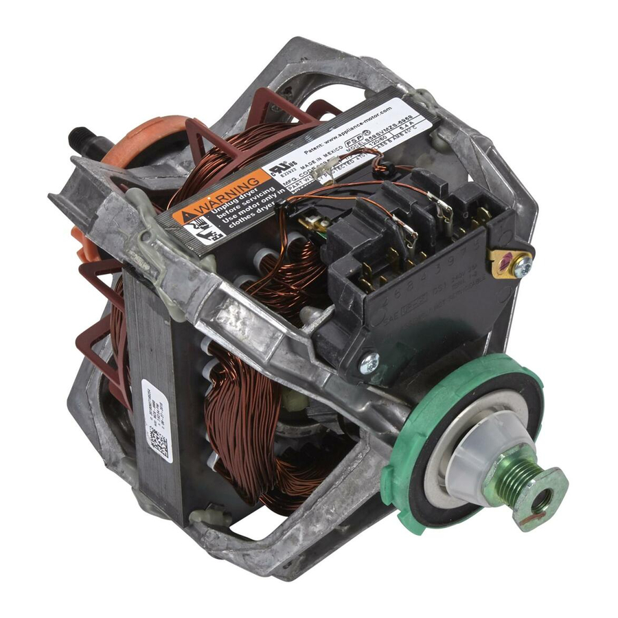
- Page 1 (6)- (110 SOURCE) DRYER MOTOR KIT #279787.
-
Page 2: Installation And Wiring
INSTALLATION AND WIRING INSTRUCTIONS for Pluggable Motor Replacement - _ 7q'1ul ThlsKitContains: Motor Assembly 3 • _ _"_" _ _/' 2 Vg' Female Tem!lnals(Insulated) 3 3 q E q _ I Sheet, I_slr_oUon _ _€_ -1 8 I" NOTETOTHEINSTALLER: Thlsm The motor m this kit may or mw not be Identical to your old motor. - Page 3 Positionmotoras shown in Figure 2. Note the location of the motor switch.Secure motor to bradder with the origim_ motor damps, .yVIRING INSTRUCTIONS NOTE: Read =rid follow Instructions unit you are replacing the motor on has the option which included the momentary switches for the drum, proceed to section title WlRIN_3JNSTRUCTIONS--- MOMENTARY...
- Page 4 Strip w_ee back approximately 1/4 of an indl. W_h ba_el crimpers, _lmp _/*" ir_vteted female ten_nlnal$, Incluclecl w ith motor, ontothe wire leads NOTE: Make sure terminals are crimped securely In place. Connect the white(SM) wire lead ontothe i/€ terminal marked "5"...


