Sign In
Upload
Manuals
Brands
Panasonic Manuals
Servo Drives
MINAS-A5NL Series
Panasonic MINAS-A5NL Series Manuals
Manuals and User Guides for Panasonic MINAS-A5NL Series. We have
2
Panasonic MINAS-A5NL Series manuals available for free PDF download: Technical Reference, Reference Specifications
Panasonic MINAS-A5NL Series Technical Reference (175 pages)
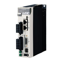
AC Servo Driver
Brand:
Panasonic
| Category:
Servo Drives
| Size: 1.34 MB
Table of Contents
Table of Contents
5
1 Introduction
9
2 Configuration and Initialization of RTEX Communication System
10
Outline
10
System Structure
10
Basic Specifications of Network
11
Node Address (MAC-ID) Setting and Front Panel Configuration
12
Communication Cycle/Command Updating Cycle, Control Mode and Data Size Setup
13
Mode Reference Table
14
Related Parameter
15
Example of Mode Setup
15
COM LED, LINK LED and RTEX Communication State
16
3 Transmission Protocol of RTEX Communication Data
17
Transmission Timing of Data
17
Transmission Timing of Communication Period 0.5 Ms/Command Updating Period 0.5 Ms
18
Transmission Timing of Communication Cycle 0.5 Ms/Command Updating Cycle 1.0 Ms
18
Transmission Timing of Communication Cycle 0.1666 Ms/Command Updating Cycle 0.1666 Ms
19
Transmission Timing of Communication Cycle 0.0833 Ms/Command Updating Cycle 0.1666 Ms
19
Transmission Timing of Communication Cycle 1.0 Ms/Command Updating Cycle 1.0 Ms
20
Transmission of Cyclic Data
21
Cyclic Transmission Area
21
Transmission of Non-Cyclic Data
22
Non-Cyclic Transmission Area
22
Non-Cyclic Status Flag
23
Non-Cyclic Command Startup Mode Setting
24
Startup of Non-Cyclic Command (MINAS-A4N Compatible Mode)
25
Basic Sequence of Non-Cyclic Command
26
Read Sequence of Non-Cyclic Command
27
Write Sequence of Non-Cyclic Command
28
Startup of Non-Cyclic Command (Extend Mode)
29
4 RTEX Communication Data Block
30
Transmission and Reception Memory in MNM1221
30
Command Data Block Arrangement (16-Byte/32-Byte Mode)
31
Command Code and Command Argument (Command Bytes 1, 415)
32
TMG_CNT Setup and Inter-Axis Synchronous Mode
33
Command Header (Command Byte 0)
35
Update_Counter Setup
35
Control Bit (Command Bytes 2 and 3)
36
Servo_On/Off Command (Servo_On)
37
Gain Switching Command (Gain_Sw)
38
Thrust Limit Switching Command (TL_SW)
39
Speed Limit Switching Command (SL_SW)
40
External Output Signal Operation Instruction (EX-OUT 1/2)
41
Data Block in Response (16-Byte/32-Byte)
42
Command_Code_Echo and Response_Data (Response Byte 1, 4 to 15)
43
Response Header (Response Byte 0)
44
Status Flag (Response Byte 2)
45
For Details, Refer to Technical Reference, SX-Dsv02309"Section 4-2-4,9-1", Functional Specification
46
Servo Ready State (Servo_Ready)
46
Internal Position Command Generation State (In_Progress)/Main Power off Alarm State (AC_OFF)
46
Servo-On in Case of Magnetic Pole Position Estimation Method
47
Command Data Block of Sub-Command (Only for 32-Byte Mode)
50
Sub-Command Code and Sub-Command Argument (Command Bytes 16 to 31)
51
Response Data Block of Sub-Command (Only for 32-Byte Mode)
52
Sub-Command Code Echo and Response Data (Command Bytes 16 to 31)
53
5 Cyclic Command Description
54
Cyclic Command List [Under Review]
54
NOP Command (Command Code: 0H)
55
Profile Position Control (PP) Command (Command Code: 1H)
56
Cyclic Position Control (CP) Command (Command Code: 2H)
57
Cyclic Velocity Control (CV) Command (Command Code: 3H)
58
Cyclic Thrust Control (CT) Command (Command Code: 4H)
59
6 Non-Cyclic Command Description
60
Non-Cyclic Command List [Under Review]
60
Normal Command (Command Code: 0H)
61
Reset Command (Command Code: 1H)
62
Software Reset Mode (Type_Code: 001H)
63
Attribute C Parameter Validation Mode (Type_Code: 011H)
64
System ID Command (Command Code: 2H)
65
System ID Command Type_Code List
66
Example of Reading of Vendor Name ("Panasonic")
67
Device Type
67
Servo Driver Type
68
Homing Command (Command Code: 4H)
69
Type Code List of Homing Command
70
Assignment of External Input Signals Related to Return to Home Sequence
72
Actual Position Setup and Command Position Setup
73
Latch Mode
75
Starting/Canceling Latch Mode
75
Selecting Latch Trigger Signal
75
Checking Latch Mode Complete Status and Latch Position Data
76
Alarm Command (Command Code: 5H)
77
Alarm Command Type_Code List
78
Setting up of Alarm Code
81
Alarm Attribute
81
Parameter Command (Command Code: 6H)
82
Type Code List of Parameter Command
83
Parameter Number of MINAS-A5N Series
85
Parameter Number of MINAS-A5N Series
86
Parameter Attribute of MINS-A5N Series
87
Protecting Parameter Writing/Eeprom Writing through RTEX
87
Profile Command (Command Code: 17H)
88
Profile Command Type_Code List
90
Selection of Latch Trigger Signal for Positioning Profile Position Latch
91
Checking Latch Mode Complete Status and Latch Position Data
91
Stop Command
92
Profile Positioning Neighborhood Output (NEAR)
93
Software Limit (PSL/NSL)
94
Other Precautions Related to Profile Command
95
Monitor Command (Command Code: Ah)
96
Type Code List of Monitor Command [Under Review]
97
Cause of no Movement
100
Assignment of the Warning Flag
101
Position Information During Servo Off, Velocity Control and Thrust Control
101
Status of Input and Output Signals
102
Command Error (Command Code: H)
105
Command Error Detection
106
Command Error Common to 16-Byte and 32-Byte Modes
106
Command Error in 32-Byte Mode
108
List of Command Error Code
109
Communication Error (Command Code: H/ Response Code: Ffh)
110
7 Operation
111
Cyclic Position Control (CP) Operation
111
Command Follow-Up Process (Command Position at Servo-Off)
111
Countermeasure for Vibration When Completion of Magnetic Pole Position Estimation
112
Prohibited Matter of NOP Command (0H)
115
Command Position Upon Communication Error
115
Variations in Command Position During Command Updating Period
116
Limiting Variations in Command Position
116
Wrap Rounding Command Position
116
Clearing Position Deviations
116
Homing Operation
117
Normal Return-To-Home Sequence in Cyclic Position Control (CP) Mode
118
Sequence of Actual Position/Command Position Setup
119
Example of Cyclic Homing Operation
121
Example of Cyclic Homing Operation 1
122
Example of Cyclic Homing Operation 2
124
Example of Cyclic Homing Operation 3
126
Example of Cyclic Homing Operation 4
127
Cyclic Velocity Control (CV) Operation
128
Cyclic Thrust Control (CT) Operation [Under Review]
130
Profile Position Control (PP) Operation
132
Profile Position Control (PP) Related Parameter
132
Profile Absolute Positioning (Type_Code: 10H)
133
Profile Relative Positioning (Type_Code: 11H)
135
Profile Position Latch Absolute Positioning (Type_Code: 12H)
137
Profile Position Latch Relative Positioning (Type_Code: 13H)
140
Profile Continuous Movement (JOG) (Type_Code: 20H)
141
Profile Homing 1 (HOME + Z Phase) (Type_Code: 31H)
143
Profile Homing 4(2) (HOME) (Type_Code: 34H(32H))
145
Profile Homing 5(3) (Z Phase) [Type_Code: 35H(33H)]
147
Precautions for Profile Position Control Operation
150
Control Mode Switching
152
Control Mode Switching Method
152
Precautions for Control Mode Change During Operation
153
Other Precautions Related to Control Mode Switching
154
Feedforward Function
155
Feedforward Function Validation Parameter and Command Area to be Used
155
Setting Unit and Setting Range
157
Compatible Control Mode
157
Other Precautions Related to Feedforward Function
158
8 RTEX Communication Related Protective Function and Troubleshooting
159
RTEX Communication Related Protective Function
159
RTEX Node Address Setting Error Protection (Err. 82.0)
160
RTEX Continuous Communication Error Protection 1 (Err. 83.0)
161
RTEX Continuous Communication Error Protection 2 (Err. 83.1)
162
RTEX Communication Timeout Error Protection (Err. 84.0)
163
RTEX Synchronization and Initialization Error Protection (Err. 84.3)
164
RTEX Communication Cycle Error Protection (Err. 84.5)
165
RTEX Cyclic Data Error Protection 1/2 (Err. 86.0/Err. 86.1)
166
Rtex_Update_Counter Error Protection (Err86.2)
167
RTEX Interaxis Sync Establishment Error Protection (Err90.2)
168
RTEX Command Error Protection (Err91.1)
169
RTEX Hardware Error Protection 1/2/3 (Err. 98.1/Err. 98.2/Err. 98.3)
170
RTEX Communication Warnings
171
RTEX Continuous Communication Error Warning (Wngc0H)
171
RTEX Accumulated Communication Error Warning (Wngc1H)
172
RTEX Update_Counter Error Warning (Wngc2H)
173
Locating Disconnection Point of Network Cable
174
Advertisement
Panasonic MINAS-A5NL Series Reference Specifications (85 pages)
AC servo driver
Brand:
Panasonic
| Category:
Servo Drives
| Size: 2.79 MB
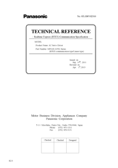
Table of Contents
Table of Contents
3
1 Scope
4
2 Product Number
4
3 Product Line-Up
5
4 Specifications
6
Basic Specifications
6
Compatible Standard (under Contemplation)
6
5 Dimensions
7
6 Appearance and Part Names
15
7 Configuration of Connectors and Terminal Blocks
24
Power Connector XA , XB , XC , XD and Terminal Block
24
USB Connector X1
27
RTEX Connectors X2A and X2B
28
Safety Function Connector X3 (for MINAS-A5N9 Series)
28
I/O Connector X4
29
Feedback Scale Connector X5
31
CS Signal Connector X6
31
Monitor Connector X7
32
8 Wiring
35
Used Cables and Maximum Cable Lengths
35
Cable Side Connector
35
Precautions for Wiring
36
9 Compliance with European EC Directive/Ul Standard
55
European EC Directive
55
Peripheral Device Configuration
56
List of Peripheral Devices Applicable to Servo Driver
58
Compliance with UL Standard
60
10 Compliance with SEMI F47 Instantaneous Stop Standard
60
11 Compliance with KC Mark
60
12 Safety Precautions
61
13 Life and Warranty
65
Life Expectancy of the Driver
65
Typical Life
65
Warranty Period
65
14 Others
66
Specification for each Model
68
Advertisement
Related Products
Panasonic MINAS-A4N
Panasonic MINAS-A5B Series
Panasonic MINAS-A6 Series
Panasonic MINAS-A6B Series
Panasonic MINAS-A5BL Series
Panasonic MBDDT2110
Panasonic MFDDTB3A2N
Panasonic MBDLN21BL
Panasonic MFDLNA3BL
Panasonic MSME Series
Panasonic Categories
Camcorder
Air Conditioner
TV
Digital Camera
Cordless Telephone
More Panasonic Manuals
Login
Sign In
OR
Sign in with Facebook
Sign in with Google
Upload manual
Upload from disk
Upload from URL