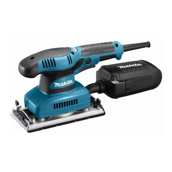
Makita BO3710 Technical Information
Finishing sander
Hide thumbs
Also See for BO3710:
- User manual ,
- Instruction manual (45 pages) ,
- Instruction manual (21 pages)
Advertisement
Quick Links
Download this manual
See also:
Instruction Manual
T
ECHNICAL INFORMATION
Model No.
Description
C
ONCEPT AND MAIN APPLICATIONS
Models BO3710 and BO3711 have been developed as
the successor models of BO3700.
Additionally to the same lightweight design as BO3700,
BO3710 and BO3711 feature the following conveniences:
Lower total height from the base to the top of the grip
for easier handling and higher maneuverability
Ergonomic tool body for sure grip and easy handling
whether in single- or double-handed operation
Easy-to-operate paper clamp with rolled clamper's edges
The specification difference between BO3710 and BO3711 is;
BO3710: Single speed model
BO3711: Variable speed model
S
pecification
Voltage (V)
110
120
220
230
240
Specification
Abrasive paper size: mm (")
Pad size: mm (")
Orbits per minute: min.
Strokes per minute: min.
Paper fastening system
Variable speed control by dial
Double insulation
Power supply cord: m (ft)
Net weight
: kg (lbs)
*2
*1 Optional pad complete (Hook & loop type) is required.
*2 Weight according to EPTA-Procedure 01/2003
S
tandard equipment
Abrasive paper 93-120 .............. 1
Punch plate ................................ 1
Dust bag or Dust box ................ 1
Note: The standard equipment for the tool shown above may vary by country.
O
ptional accessories
Abrasive papers 93-60, 93-80, 93-120, 93-180, 93-240 (Clamp type)
Abrasive papers 93-60, 93-80, 93-120, 93-180, 93-240 (Hook & loop type)
Punch plate
Hose complete 28-1.5
Pad complete (Clamp type)
Pad complete (Hook & loop type)
Filter set (including 5 non-woven cloth filters)
BO3710, BO3711
Finishing Sander
Cycle (Hz)
Current (A)
1.8
50/60
1.7
50/60
0.95
50/60
0.85
50/60
0.85
50/60
Model No.
= opm
-1
= spm
-1
Hook & loop
Clamp
Continuous Rating (W)
Input
190
---
190
190
190
BO3710
93 x 228 (3-5/8 x 9)
93 x 185 (3-5/8 x 7-1/4)
11,000
4,000 - 11,000
22,000
8,000 - 22,000
Yes
*1
Yes
No
Yes
2.0 (6.6)
1.6 (3.5)
H
W
Dimensions: mm (")
Length (L)
Width (W)
Height (H)
154 (6-1/16)
Max. Output (W)
Output
70
70
70
70
70
BO3711
Yes
1.6 (3.5)
PRODUCT
P
1/ 7
L
253 (10)
92 (3-5/8)
80
80
80
80
80
Advertisement

Summary of Contents for Makita BO3710
- Page 1 BO3710, BO3711 Description Finishing Sander ONCEPT AND MAIN APPLICATIONS Models BO3710 and BO3711 have been developed as the successor models of BO3700. Additionally to the same lightweight design as BO3700, BO3710 and BO3711 feature the following conveniences: Lower total height from the base to the top of the grip for easier handling and higher maneuverability Dimensions: mm (")
-
Page 2: Necessary Repairing Tools
P 2/ 7 epair CAUTION: Repair the machine in accordance with “Instruction manual” or “Safety instructions”. [1] NECESSARY REPAIRING TOOLS Code No. Description Use for 1R027 Bearing setting pipe 18-10.2 Removing Armature 1R029 Bearing setting pipe 23-15.2 Removing Balancer from Base 1R258 V block Holding Ball bearing 6202DDW when removing Balancer 1R269 Bearing extractor... - Page 3 P 3/ 7 epair [3] DISASSEMBLY/ASSEMBLY [3]-1. Armature (cont.) DISASSEMBLING 7) Armature can be removed from Bearing box by tapping the shaft with plastic hammer. (Fig. 7A) Note: When it is difficult to remove Armature in the above manner, put 1R027 on Ball bearing 6200DDW and press down 1R027 as illustrated in Fig.
- Page 4 P 4/ 7 epair [3]-2. Ball bearing 6202DDW, Balancer DISASSEMBLING 1) Remove Pad complete by unscrewing four M4x10 Pan head screws. Note: It is not necessary to remove Top cap. 2) Remove Base section from the machine by unscrewing M5x16 Countersunk head screw. 3) Disassemble Base section as illustrated in Fig.
- Page 5 P 5/ 7 epair [3] DISASSEMBLY/ASSEMBLY [3]-3. Field ASSEMBLING 1) Facing the red lead wire side to Front grip side, assemble Field as illustrated in Fig. 13. 2) As for the further step, take the reverse step of Disassembly. Fig. 11 Front grip Front grip side Red Lead wire...
-
Page 6: Circuit Diagram
P 6/ 7 ircuit diagram ( BO3710 without pre-set Dial for Speed Control Fig. D-1 Front grip side Color index of lead wires' sheath Black White Field Brush holder Switch Noise suppressor Brown Lead wire is used Blue Lead wire is used for some countries. - Page 7 P 7/ 7 ircuit diagram ( BO3711 with pre-set Dial for Speed Control Fig. D-3 Front grip side Color index of lead wires' sheath Black White Field Brush holder Controller Insulated connector White Lead wire is used for some countries. Noise suppressor Brown Lead wire is used for some countries.


